


Quick Research
Generate reliable direction feasibility study reports for your R&D in just a few steps.

Technical Q&A
Discover and master advanced knowledge NOW. Basics, ideas, possibilities, all at once.

Find Solutions
As an expert in R&D theories, this can generate solutions to your technical problems instantly.

Evaluate Feasibility
Analyze your overall solution with one click, know your potential R&D risks in advance.

Monitor Landscape
Get weekly tech updates, stay abreast of the latest tech innovations and key insights.
Layered rotor structure for high-speed permanent magnet motor and manufacturing method
A permanent magnet motor, rotor structure technology, applied in the magnetic circuit shape/style/structure, manufacturing motor generators, magnetic circuit rotating parts, etc., can solve the limitation of the maximum power and maximum speed of the lifting space, air gap magnetic field waveform High harmonic content, increased motor eddy current loss, etc., to avoid excessive local stress, reduce air friction loss, and reduce eddy current loss.
- Summary
- Abstract
- Description
- Claims
- Application Information
AI Technical Summary
Problems solved by technology
Method used
Image

Examples
Embodiment 1
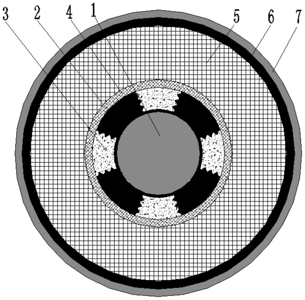
[0034] Such as Figure 1 to Figure 4As shown, a layered rotor structure for a high-speed permanent magnet motor, including a rotor core 1, a permanent magnet 2 and a protective sleeve arranged radially from the inside to the outside, the permanent magnet 2 is a rare earth permanent magnet, and the permanent magnet 2 includes a ring base, the outer circular surface of the ring base is integrally formed with an outwardly protruding block along the circumferential direction, and the contact surface between the block and the block ferrite material filling body 3 is processed radially with a plurality of triangular cross-sections The permanent magnet 2 is set on the outer surface of the rotor core 1, and the permanent magnet 2 is fixed by bonding. The permanent magnet 2 generally has a large residual magnetism and produces a large air gap magnetic density. Because its position is average The radius is small, so the stress by the centrifugal force is very small, which can effectivel...
Embodiment 2
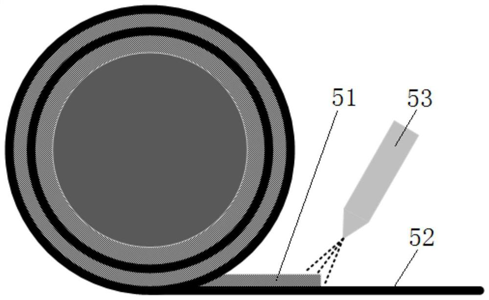
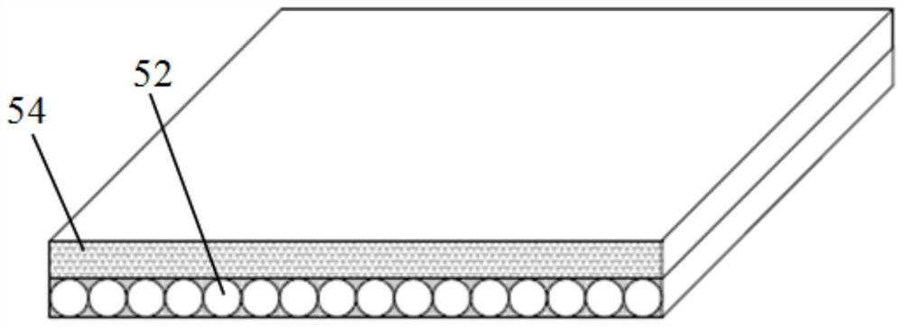
[0042] The difference between this embodiment and embodiment 1 is that, as Figure 5 As shown, the mixed layer 5 is a variable-thickness layer 56, that is, the mixed layer 5 is a multi-layer variable-thickness structure, that is, a structure in which the inner layer is thick and the outer layer is thin. By adjusting the spraying amount of the adhesive film prefabricated material 51 , and then adjusting the thickness of the flexible magnetic powder adhesive film 54 , the carbon fiber prewound tape forms a variable thickness structure.
[0043] Due to the small radius of the inner layer, the local stress generated by the centrifugal force of the same volume carbon fiber pre-wound tape is small. Therefore, when making the carbon fiber pre-wound tape bonded to the inner layer, the amount of spraying of the adhesive film prefabricated material 51 is reduced to reduce the amount of flexible magnetic powder. The thickness of the adhesive film 54 makes the volume of the magnetic powde...
Embodiment 3
[0045] The difference between this embodiment and embodiment 1 is that, as Figure 6 As shown, the mixed layer 5 is a mixed structure of an equal thickness layer 55 and a variable thickness layer 56, including an inner layer and an outer layer distributed along the direction, that is, the inner layer of the mixed layer 5 is a variable thickness layer 56, and the inner layer of the mixed layer 5 is a variable thickness layer 56. The outer layer is a constant thickness layer 55 .
PUM
| Property | Measurement | Unit |
|---|---|---|
| Thickness | aaaaa | aaaaa |
| Thickness | aaaaa | aaaaa |
| Single layer thickness | aaaaa | aaaaa |
Abstract
Description
Claims
Application Information
 - R&D Engineer
- R&D Manager
- IP Professional
- Industry Leading Data Capabilities
- Powerful AI technology
- Patent DNA Extraction
Browse by: Latest US Patents, China's latest patents, Technical Efficacy Thesaurus, Application Domain, Technology Topic, Popular Technical Reports.
© 2024 PatSnap. All rights reserved.Legal|Privacy policy|Modern Slavery Act Transparency Statement|Sitemap|About US| Contact US: help@patsnap.com