Thermal power plant combined type heat pipe smoke residual heat recycling device

A waste heat recovery and recovery device technology, which is applied to heat exchange equipment, heat exchanger shells, indirect heat exchangers, etc., can solve the problem of inability to perform gas temperature control at the heat absorption end, inability to accurately control heat exchange energy, and low energy conversion rate and other problems, to achieve the effect of easy maintenance and replacement, improvement of waste heat recovery efficiency, and simple cleaning

Active Publication Date: 2020-11-24
HUAINAN TIANJIAAN POWER GENERATION PLANT ANHUI ELECTRIC POWER CO LTD
View PDF7 Cites 3 Cited by
  • Summary
  • Abstract
  • Description
  • Claims
  • Application Information

AI Technical Summary

Problems solved by technology

[0005] However, the existing flue gas waste heat recovery devices in thermal power plants generally adopt the heat pipe recovery method, the structure is too simple, the practicability is low, the energy conversion rate is low, and the heat exchange energy cannot be precisely controlled, that is, the gas at the heat absorption end cannot be controlled. Temperature control, low practicability. In addition, the traditional heat pipe waste heat recovery device can only realize a single "gas-gas" or "gas-liquid" waste heat recovery function, which has certain defects.

Method used


Image

  • Thermal power plant combined type heat pipe smoke residual heat recycling device
  • Thermal power plant combined type heat pipe smoke residual heat recycling device
  • Thermal power plant combined type heat pipe smoke residual heat recycling device

Examples


Embodiment Construction

[0029] The technical solutions in the embodiments of the present invention will be clearly and completely described below with reference to the accompanying drawings in the embodiments of the present invention. Obviously, the described embodiments are only a part of the embodiments of the present invention, but not all of the embodiments. Based on the embodiments of the present invention, all other embodiments obtained by those of ordinary skill in the art without creative efforts shall fall within the protection scope of the present invention.

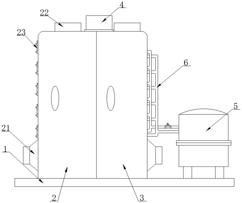
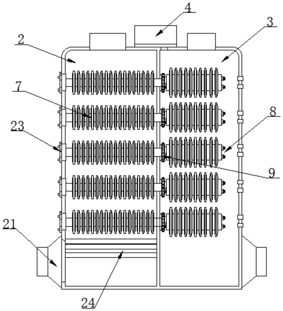
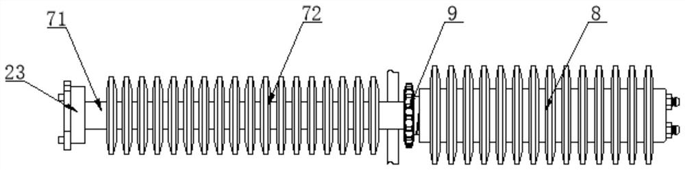
[0030] as attached Figure 1-7 A thermal power plant combined heat pipe flue gas waste heat recovery device is shown, including a mounting seat 1, a flue gas discharge bin 2 and a waste heat recovery bin 3, and the flue gas discharge bin 2 and the waste heat recovery bin 3 are fixedly installed on the top of the mounting seat 1. The side and top surfaces of the flue gas discharge bin 2 and the waste heat recovery bin 3 are respectivel...


PUM


Abstract

The invention discloses a thermal power plant combined type heat pipe smoke residual heat recycling device and particularly relates to the field of residual heat recycling. The thermal power plant combined type heat pipe smoke residual heat recycling device comprises an installation seat, a smoke discharging bin and a residual heat recycling bin, wherein the top face of the installation seat is fixedly provided with a heat exchange water box, the smoke discharging bin and the residual heat recycling bin are fitted to each other on one side and are internally provided with combined type heat pipes in a running through manner, the surfaces of the combined type heat pipes are rotatably connected with screw thread driving sleeves located inside the smoke discharging bin in a sleeved manner, and the surfaces of the screw thread driving sleeves are movably connected with heat exchange pipe sleeve components in a sleeved manner. The thermal power plant combined type heat pipe smoke residual heat recycling device is provided with novel combined type heat pipe structures, the heat conduction fluid flow volume inside the heat exchange pipe sleeve components is actively changed by utilizing amechanical control component, and the bare lengths of the heat pipe ends inside the residual heat recycling bin are changed, heat exchange efficiency control is realized, the heat recycling airflow temperature is changed, precise temperature control is realized, use of recycled heat energy is facilitated, and the practicability of the residual heat recycling device is improved.

Description

technical field [0001] The invention relates to the technical field of waste heat recovery, in particular to a thermal power plant combined heat pipe flue gas waste heat recovery device. Background technique [0002] In recent years, my country's energy demand has shown a rigid growth. Due to the constraints of domestic resource security capabilities and environmental capacity, as well as global energy security and the impact of climate change, resource and environmental constraints have become increasingly intensified. The situation faced by energy conservation and emission reduction is very severe. In the production process of thermal power plants , coal-fired boilers generally have problems such as low heat utilization rate, high waste heat temperature of exhaust flue gas, and high pollution gas content in flue gas. The use of waste heat recovery system can effectively solve the above problems. [0003] Waste heat resources are secondary resources, which are energy that ma...

Claims


Application Information

Patent Timeline
IPC IPC(8): F28D15/02F28D15/06F28F9/26F28F19/01F23J15/06
CPCF28D15/0275F28D15/06F28F9/26F28F19/01F23J15/06Y02E20/30
Inventor 刘彬杨泉胡鲲刘刚王荣胜
Owner HUAINAN TIANJIAAN POWER GENERATION PLANT ANHUI ELECTRIC POWER CO LTD
Why Eureka
Try Eureka