
Magnetic control sucker device and using method thereof

A suction cup and magnetic control technology, applied in the direction of magnets, suction cups, permanent magnets, etc., can solve problems such as use, unfavorable medical fields, and inability to be easily removed, and achieve the effects of simple device structure, expanded use range, and convenient operation

Active Publication Date: 2020-11-24
CHINA UNIV OF PETROLEUM (EAST CHINA)
View PDF23 Cites 1 Cited by
  • Summary
  • Abstract
  • Description
  • Claims
  • Application Information

AI Technical Summary

Problems solved by technology

At present, most suction cups need to be adsorbed on the surface of the substrate by extrusion. It is inevitable that the adsorption strength of the suction cup will be controlled by direct contact during use, which is not conducive to the use in the medical field, and once adsorbed, it cannot be easily removed.
[0003] In addition, some suction cups carry air pumps, through which the air in the suction cups is drawn to generate negative pressure, so that the suction cups are adsorbed on the surface of the substrate, and then the suction cups are desorbed through the deflation of the air pump. Higher sealing requirements

Method used


Image

  • Magnetic control sucker device and using method thereof
  • Magnetic control sucker device and using method thereof
  • Magnetic control sucker device and using method thereof

Examples


preparation example Construction

[0054] More specifically, the preparation method of the hard magnetic floppy disk comprises the following steps:

[0055] a) Take two-component silica gel and hard magnetic particles and mix them to obtain a mixed solution;

[0056] b) Pour the above mixed solution into a circular petri dish, then place the round petri dish in a vacuum drying oven, vacuumize it, and let it stand to obtain a hard magnetic floppy disk after curing;

[0057] c) Magnetizing the hard-magnetic floppy disk, applying a high-intensity parallel magnetic field along the thickness direction of the hard-magnetic floppy disk to obtain a magnetized hard-magnetic floppy disk.

[0058] Further, in step a), the mixing is stirring in a mixer, the stirring speed is 600-700rpm, and the stirring time is 5 minutes;

[0059] In step b), the vacuuming time is 5 to 20 minutes, and the standing time is 1 to 6 hours;

[0060] In step c), the intensity of the magnetic field is 1-2T, and the magnetization time is 5-10 mi...

Embodiment 1

[0072] Example 1 A method of using a magnetically controlled chuck for adsorption

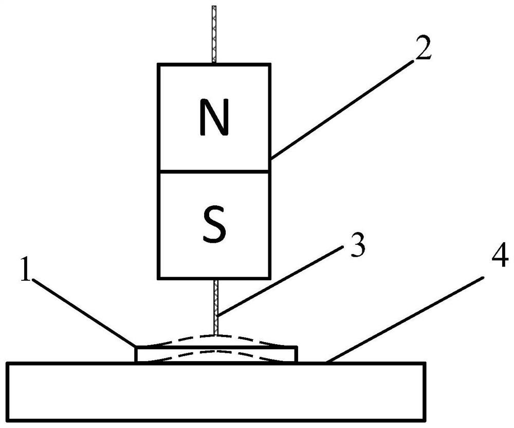
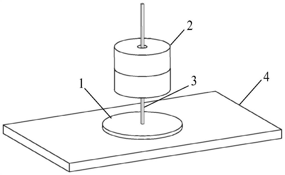
[0073] The magnetically controlled chuck comprises: a disc-shaped hard magnetic floppy disk, a cylindrical magnet (NdFeB permanent magnet), and a rope, wherein the hard magnetic floppy disk 1, the magnet piece, and the rope are coaxially arranged.

[0074] Specific adsorption methods include:

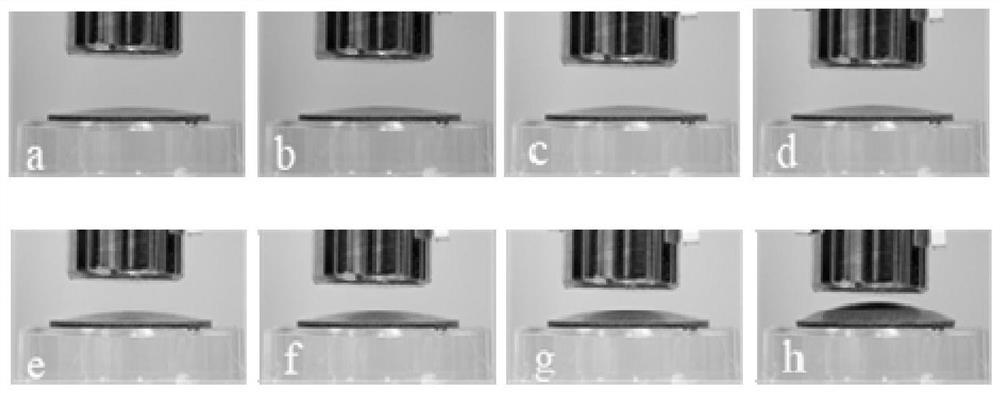
[0075] The magnet and the hard magnetic floppy disk are approached in the same way with the same magnetic poles, and the distance between the magnet and the hard magnetic floppy disk is adjusted to 22mm to control the adsorption strength of the hard magnetic floppy disk to the adsorbed substance, so as to realize the hard magnetic floppy disk for the adsorbed substance. adsorption;

[0076] When the hard magnetic floppy disk needs to be desorbed from the substance to be adsorbed, the rope is pulled to realize desorption.

Embodiment 2~8

[0078] Same as embodiment 1, the difference is that the distances between the magnet parts and the hard magnetic floppy disk are 20mm, 18mm, 16mm, 14mm, 12mm, 10mm, 8mm respectively.


PUM

PropertyMeasurementUnit
Particle sizeaaaaaaaaaa

Abstract

The invention provides a magnetic control sucker device and a using method thereof, and relates to the technical field of suckers. The magnetic control sucker device comprises: a hard magnetic floppydisk for attracting a substance to be attracted, a magnet piece and a rope, wherein the magnet piece is used for providing a magnetic field function for a hard magnetic floppy disk, and the magnet piece and the substance to be attracted are positioned on two sides of the hard magnetic floppy disk respectively; and the rope is used for pulling the hard magnetic floppy disk. The magnetic control sucker device can be used in the field of medical instruments, and has the advantages of being simple in structure, novel in design, controllable in attraction strength, low in maintenance cost, safe andenvironmentally friendly.

Description

technical field [0001] The invention relates to the technical field of chucks, in particular to a magnetically controlled chuck device and a method for using the same. Background technique [0002] A suction cup is a tool that uses the pressure difference between the inside and outside of the atmosphere to absorb or grab objects. At present, most suction cups need to be adsorbed on the surface of the substrate by extrusion. It is inevitable that the suction strength of the suction cup will be controlled by direct contact during use, which is not conducive to the use in the medical field, and once adsorbed, it cannot be easily removed. [0003] In addition, some suction cups carry air pumps, through which the air in the suction cups is drawn to generate negative pressure, so that the suction cups are adsorbed on the surface of the substrate, and then the suction cups are desorbed through the deflation of the air pump. Higher sealing requirements. Contents of the invention ...

Claims


Application Information

Patent Timeline
IPC IPC(8): F16B47/00H01F7/02
CPCF16B47/00H01F7/0242
Inventor 刘建林程永桂罗偲徐香玲张云
Owner CHINA UNIV OF PETROLEUM (EAST CHINA)
Learn More