Green airport intelligent aircraft tractor
A smart aircraft and tractor technology, applied in aircraft parts, battery/battery traction, electric vehicles, etc., can solve the problem of unresolved turning pins, high operating and maintenance costs, and the inability of aircraft to turn when taxiing. Reduce traditional manual work steps, excellent construction and maintenance costs, and ingenious structural design
- Summary
- Abstract
- Description
- Claims
- Application Information
AI Technical Summary
Problems solved by technology
Method used
Image
Examples
Embodiment 1
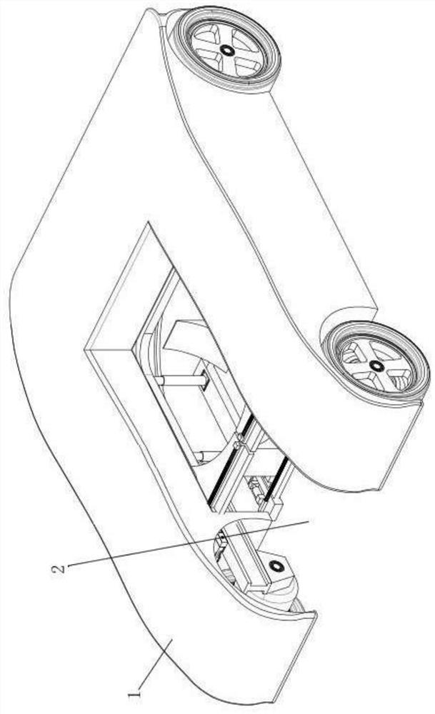
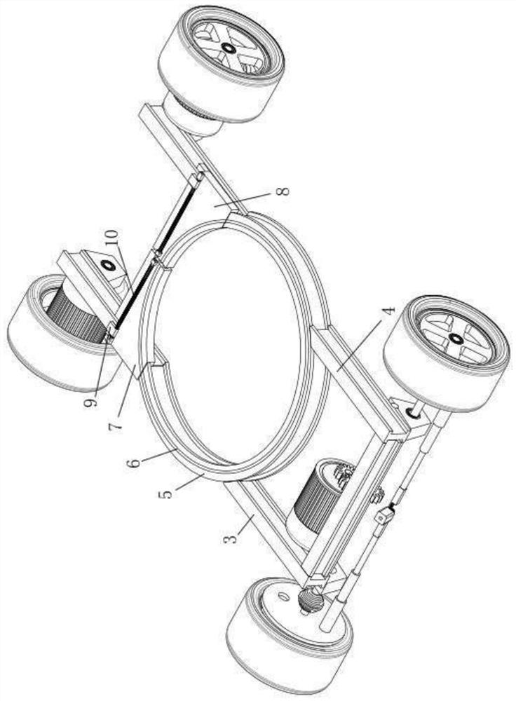
[0039] Such as Figure 1-Figure 6 As shown, the green airport intelligent aircraft tractor includes a body 1, a chassis, and an electrical control system.
[0040] Wherein, the vehicle body 1 includes parallel left and right longitudinal beams 3, 4, an annular support beam 5 arranged between the left and right longitudinal beams 3, 4, and the position of the annular support beam 5 corresponding to the front side of the vehicle body 1 is The movable end is provided with left and right movable beams 7 and 8 at the movable end. The left and right movable beams 7 and 8 are respectively supported on the left and right longitudinal beams 3 and 4, and a drive mechanism I is additionally provided between the left and right longitudinal beams 3 and 4 and the left and right movable beams 7 and 8, and the left 1. The trajectory of the right movable beam 7,8 is perpendicular to the length direction of the left and right longitudinal beams 3,4. The chassis includes a support turntable 11...
Embodiment 2
[0053] Such as Figure 7-Figure 10 Shown, this green airport intelligent aircraft tractor, the front portion of left and right longitudinal beams 3,4 is provided with the widening supporting base 33 of corresponding left and right movable beams 7,8, and described left and right movable beams 7,8 There is a slide rail structure I34 that cooperates with the widened support seat 33, the left and right movable beams 7, 8 slide along the widened support seat 33 through the slide rail structure I34, and the drive mechanism I is fixed by the widened support seat 33. The connected drive motor I39, the gear I40 fixed on the output shaft of the drive motor I39, the rack structure I41 arranged on the left and right movable beams 7 and 8 and meshed with the gear I40, the rack structure I41 is located on the left and right movable The beams 7 and 8 face away from the slide rail structure I34 side. After the drive motor I39 drives the gear I40 to rotate, the gear I40 drives the left and ri...
PUM
 Abstract
Description
Claims
Application Information
 - R&D
- Intellectual Property
- Life Sciences
- Materials
- Tech Scout
- Unparalleled Data Quality
- Higher Quality Content
- 60% Fewer Hallucinations
Browse by: Latest US Patents, China's latest patents, Technical Efficacy Thesaurus, Application Domain, Technology Topic, Popular Technical Reports.
© 2025 PatSnap. All rights reserved.Legal|Privacy policy|Modern Slavery Act Transparency Statement|Sitemap|About US| Contact US: help@patsnap.com


