
Ventilation device of air compression station cabinet

A technology of ventilation device and air compressor station, which is applied in the direction of cooling/ventilation/heating transformation, casing/cabinet/drawer parts, electrical equipment casing/cabinet/drawer, etc., which can solve the problem of rapid failure of lubricating grease and equipment Shorten the maintenance cycle and increase the maintenance cost, etc., to avoid the equipment from being damp, improve the cooling effect, and reduce the temperature quickly

Inactive Publication Date: 2020-11-20
安徽国祯生态科技有限公司
View PDF7 Cites 2 Cited by
  • Summary
  • Abstract
  • Description
  • Claims
  • Application Information

AI Technical Summary

Problems solved by technology

[0003] However, when the existing air compressor is running, the temperature of the motor, machine head and other equipment parts is high (generally 40-50°C), resulting in a high environment inside the cabinet. The original design has no axial flow fan and external exhaust air duct
The air inlet temperature of the air compressor is high, which leads to the high temperature of the exhaust outlet of the air compressor, the air compressor lubricating grease fails quickly, the equipment failure rate is high, the lubricating oil replacement cycle is short, the equipment maintenance cycle is shortened, and the equipment is reliable. Poor performance and increased maintenance costs

Method used


Image

  • Ventilation device of air compression station cabinet
  • Ventilation device of air compression station cabinet
  • Ventilation device of air compression station cabinet

Examples


Embodiment Construction

[0027] The following will clearly and completely describe the technical solutions in the embodiments of the present invention with reference to the accompanying drawings in the embodiments of the present invention. Obviously, the described embodiments are only some, not all, embodiments of the present invention. Based on the embodiments of the present invention, all other embodiments obtained by persons of ordinary skill in the art without making creative efforts belong to the protection scope of the present invention.

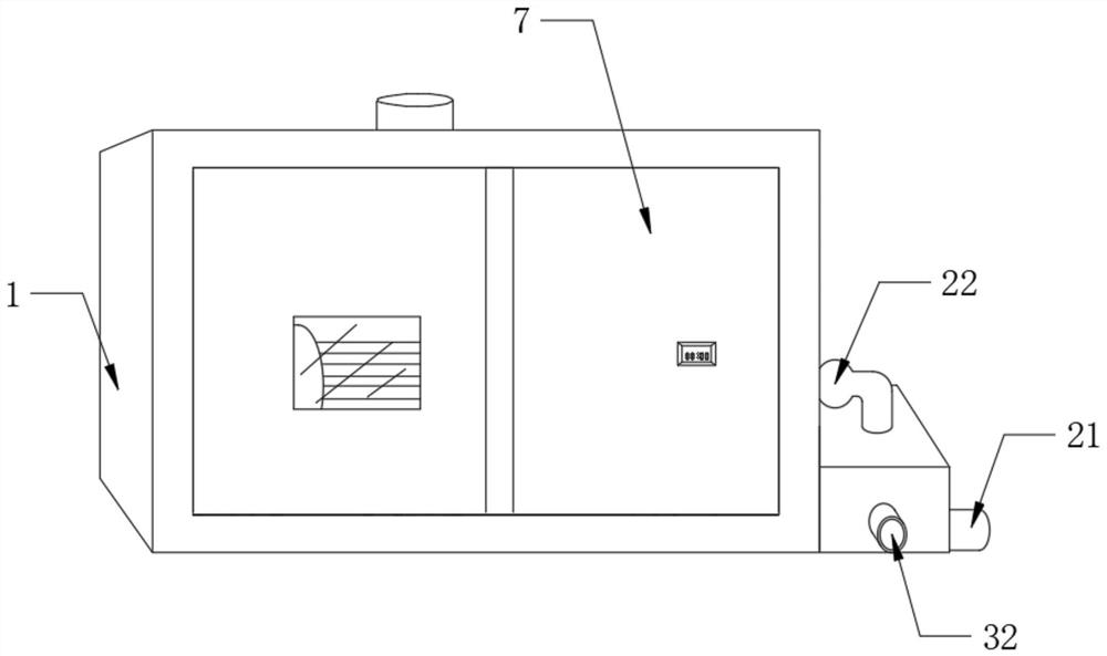
[0028] see Figure 1 to Figure 5 , the present invention provides a technical solution for the ventilation device of the air compressor station cabinet:

[0029] A ventilation device for an air compressor station cabinet, such as figure 1 As shown, it includes a cabinet body 1, the cabinet body 1 is provided with an exhaust mechanism 2, and the exhaust mechanism 2 is connected with a cooling mechanism 3;

[0030] The exhaust mechanism 2 is used for exhaustin...


PUM


Abstract

The invention discloses a ventilation device of an air compression station cabinet. The ventilation device comprises a cabinet body, an exhaust mechanism is arranged in the cabinet body, and the exhaust mechanism is connected with a cooling mechanism; the exhaust mechanism is used for air exhaust and heat dissipation in the cabinet. The cooling mechanism is used for cooling air entering the cabinet; the exhaust mechanism comprises an air inlet pipe, an air conveying pipe, a drying box and an air inlet fan. One end of the air inlet pipe is connected with the cooling mechanism; one end of the air conveying pipe is connected with the cooling mechanism; the other end of the air conveying pipe penetrates through the inner wall of the cabinet body and is connected with the lower part of the drying box in a penetrating manner; the air inlet fan is installed in the air conveying pipe; according to the ventilation device of the air compression station cabinet, the temperature in the cabinet body can be monitored in time, heat dissipation can be conducted on the cabinet body, hot air is pumped out of the cabinet body, cooling air enters the cabinet body, the cooling speed is high, air dehumidification can be conducted, and equipment in the cabinet body is prevented from being affected with damp.

Description

technical field [0001] The invention relates to the technical field of air compression equipment, in particular to a ventilation device for an air compressor station cabinet. Background technique [0002] The air compressor station is a compressed air station, which consists of an air compressor, an air storage tank (divided into primary and secondary air storage tanks), air treatment and purification equipment, and a cold dryer. Compressed air is the most environmentally friendly power in industrial production Source, widely used in medicine, food, machinery, electronics, plastics, textiles, electric power, building materials and other industries, as spraying, mixing, conveying and so on. [0003] However, when the existing air compressor is running, the temperature of the motor, machine head and other equipment parts is high (generally 40-50°C), resulting in a high environment inside the cabinet. The original design has no axial flow fan and external exhaust air duct. The...

Claims


Application Information

Patent Timeline
Patent Type & Authority Applications(China)
IPC IPC(8): H05K5/02H05K7/20B01D53/26B01D53/28
CPCH05K5/0213H05K7/20145H05K7/20181B01D53/261B01D53/28H05K7/20272H05K5/0217H05K7/20209
Inventor 刘宏开金龙徐建东秦汉俊
Owner 安徽国祯生态科技有限公司
Learn More