Self-powered airflow sensor and production method thereof

An airflow sensor and self-powered technology, applied in the field of airflow sensors, can solve the problems of small device size, low sensitivity, and high manpower and material resources, and achieve the effect of easy integration and high sensitivity

Active Publication Date: 2020-11-20
PEKING UNIV SHENZHEN GRADUATE SCHOOL
View PDF5 Cites 0 Cited by
  • Summary
  • Abstract
  • Description
  • Claims
  • Application Information

AI Technical Summary

Problems solved by technology

In recent years, with the development of microelectromechanical systems (MEMS), airflow sensors based on MEMS technology have received more and more attention. However, such sensors still have the problems of high power consumption and low sensitivity, which seriously limit the further development of sensors. develop
Especially the problem of high power consumption, because the device size based on the MEMS process is very small (feature size 100-1000μm), replacing the battery or charging will consume a lot of manpower and material resources

Method used


Image

  • Self-powered airflow sensor and production method thereof
  • Self-powered airflow sensor and production method thereof
  • Self-powered airflow sensor and production method thereof

Examples


Embodiment 1

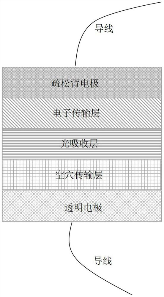
[0038] 1. Place the ITO glass in ethanol, acetone, and isopropanol for ultrasonic cleaning for 15 minutes, and then dry it with a nitrogen gun. Spin-coat PEDOT:PSS on ITO at a speed of 3000r / min for 30s, and then heat on a hot stage at 120°C for 10min, thus completing the preparation of the hole transport layer;

[0039] 2. Combine MaI and PbI 2 Dissolved in DMF:DMSO (volume ratio 4:1), stirred at 70°C for 30min to obtain 1.4mol / L perovskite MaPbI 3 Solution, spin-coat the perovskite solution on the hole transport layer. The process is to spin-coat at 1000r / min for 5s, then spin-coat at 4000r / min for 30s. In the second stage of 7s, add 350μL of toluene as anti-solvent, and then Annealing, first annealing at 60°C for 1min, then annealing at 80°C for 5min;

[0040] 3. The electron transport material PCBM was dissolved in chlorobenzene to prepare a 20mg / mL solution, and the PCBM solution was spin-coated on the perovskite layer at 600r / min for 2min. Afterwards, place the sheet ...

Embodiment 2

[0047] The structure and preparation method of the airflow sensor in this embodiment are the same as in Embodiment 1, the only difference is that the back electrode is replaced by carbon paste with silver paste, which is still prepared by screen printing process, and the obtained sensor is recorded as ITO / PEDOT:PSS / PVK / PCBM / Ag.

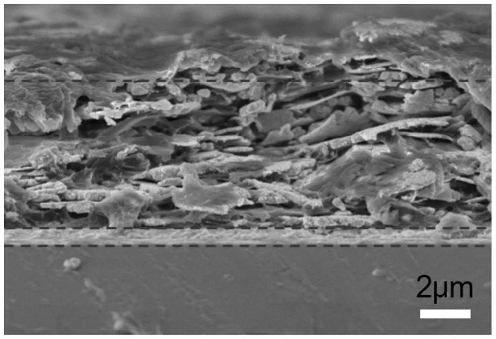
[0048] Figure 4 It is the cross-sectional electron microscope image of the sensor prepared in Example 2. It can be seen that the silver electrode prepared by the screen printing process presents a loose and porous structure, and the thickness of the back electrode is about 10 μm, which is much thicker than that prepared by the spin coating method below. The sum of the thicknesses of the electron transport layer, light absorbing layer and hole transport layer.

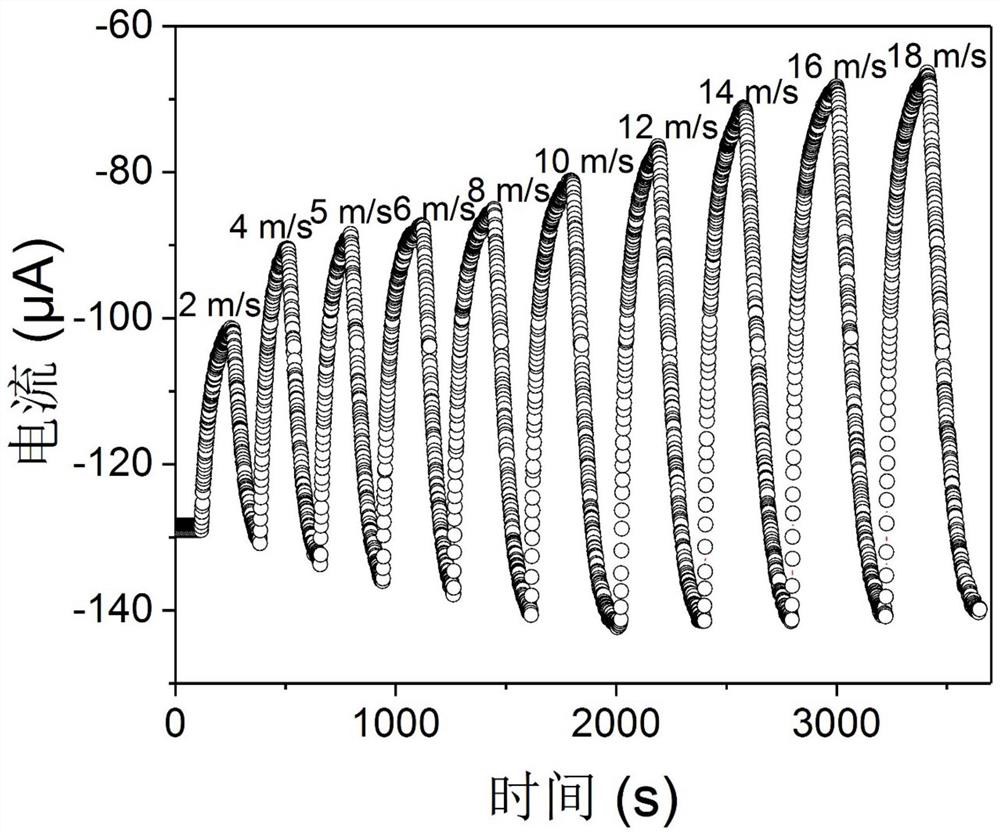
[0049] Figure 5When the ITO / PEDOT:PSS / PVK / PCBM / Ag sensor prepared in Example 2 is exposed to different flow rates, the current between the two electrodes varies with time. It can be seen ...


PUM

PropertyMeasurementUnit
thicknessaaaaaaaaaa

Abstract

The invention provides a self-powered airflow sensor based on a photovoltaic device structure and a production method thereof, belongs to the technical field of airflow sensors, and can be used for airflow velocity detection in the fields of industry, agriculture, meteorology and the like. The airflow sensor structure based on a photovoltaic device comprises a transparent electrode, a hole transport material, a light absorption material, an electron transport material and a loose porous back electrode material. The production method comprises the steps that the hole transport material, the light absorption material and the electron transport material are prepared through evaporation, atomic layer deposition or a spin-coating method, and the loose porous back electrode is prepared through asilk-screen printing method. The airflow sensor based on the photovoltaic device structure provided in the invention is self-powered, high in sensitivity, capable of being processed by a solution method, miniaturized and the like.

Description

technical field [0001] The invention belongs to the field of airflow sensors, and relates to a self-powered airflow sensor based on a photovoltaic device structure and a preparation method thereof. The sensor can be used to detect gas flow velocity in fields such as industry, agriculture, and meteorology. [0002] technical background [0003] Airflow sensors have important applications in industry, agriculture, meteorology and other fields. In recent years, with the development of micro-electromechanical systems (MEMS), airflow sensors based on MEMS technology have received more and more attention. However, such sensors still have the problems of high power consumption and low sensitivity, which seriously limit the further development of sensors. develop. Especially the problem of high power consumption, because the size of the device based on the MEMS process is very small (the characteristic size is 100-1000 μm), replacing the battery or charging will consume a lot of man...

Claims


Application Information

Patent Timeline
Patent Type & Authority Applications(China)
IPC IPC(8): H01L51/42H01L51/44B81B7/02B81C1/00G01P5/00
CPCB81B7/02B81C1/00015G01P5/00B81B2201/02H10K30/10H10K30/81Y02E10/549
Inventor 孟鸿张赫
Owner PEKING UNIV SHENZHEN GRADUATE SCHOOL
Why Eureka
Try Eureka