
Blank moving device of blowing molding machine

A technology of moving device and blow molding machine, which is applied in the field of billet moving device, and can solve the problems of manual removal of temperature, etc.

Pending Publication Date: 2020-11-20
李旭燕
View PDF4 Cites 2 Cited by
  • Summary
  • Abstract
  • Description
  • Claims
  • Application Information

AI Technical Summary

Problems solved by technology

[0003] The purpose of the present invention is to solve the problems in the prior art that manual removal is required after blow molding is completed and the temperature is too high to quickly enter the next process, and a billet moving device for a blow molding machine is proposed.

Method used


Image

  • Blank moving device of blowing molding machine
  • Blank moving device of blowing molding machine
  • Blank moving device of blowing molding machine

Examples


Embodiment 1

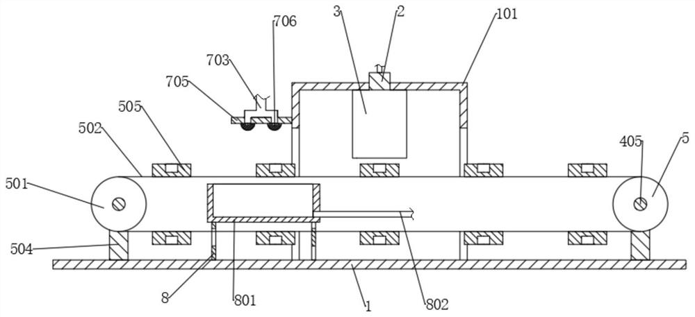
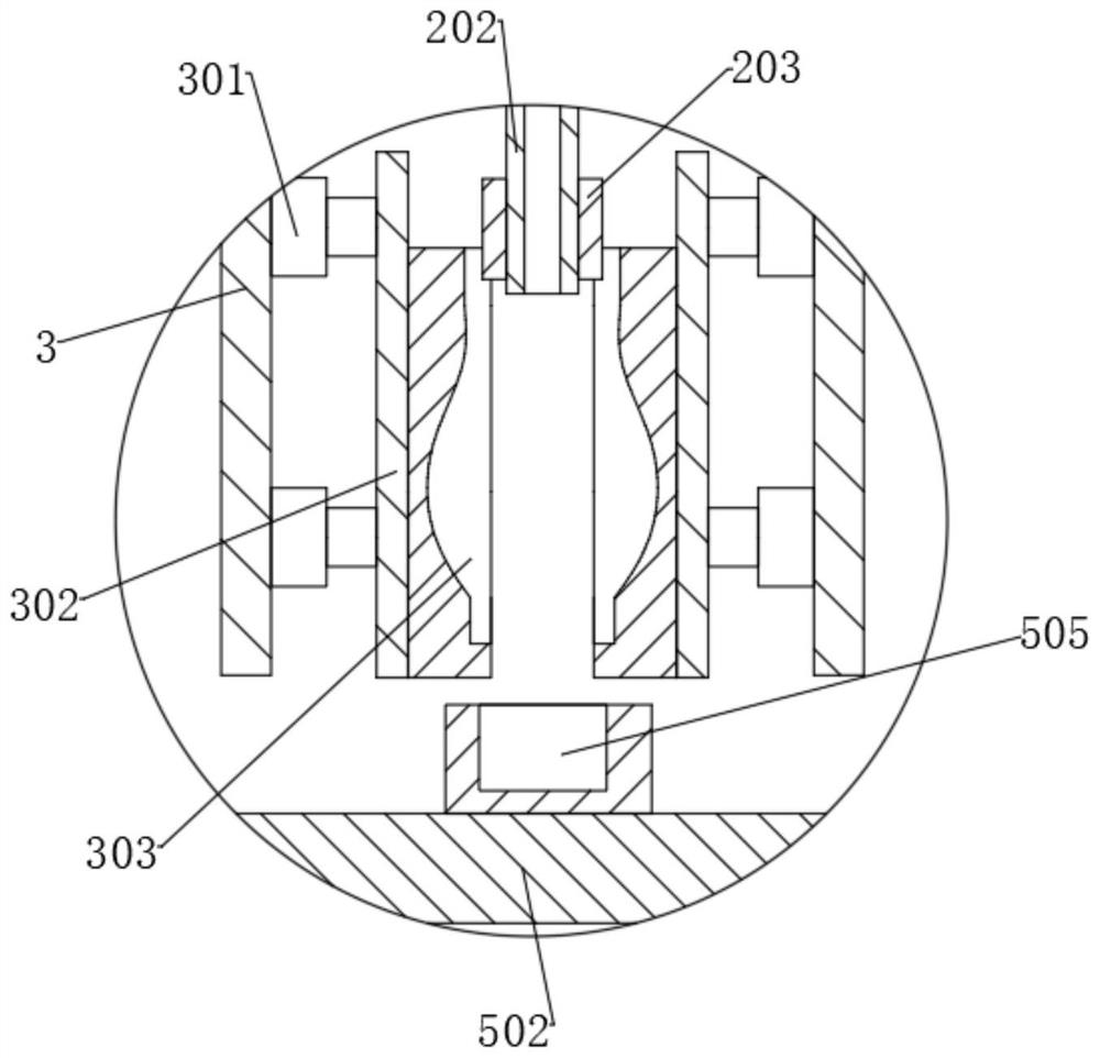
[0025] refer to Figure 1-5 , a billet moving device for a blow molding machine, comprising a bottom plate 1, a support frame 101 and a box body 102, the side wall of the box body 102 is provided with a motor 4, the output end of the motor 4 is connected to a first rotating shaft 401, and the first rotating shaft 401 The cam 402 and the first turntable 403 are respectively connected to the top, the first turntable 403 is provided with a toggle tooth 404, the side wall of the box body 102 is rotatably connected with a second rotating shaft 405, and the second rotating shaft 405 is respectively provided with a drive wheel 5 and a second rotating shaft 405. Two turntables 406, the second turntable 406 is provided with a toggle groove that cooperates with the toggle teeth 404, the base plate 1 is also provided with a driven wheel 501, a conveyor belt 502 is connected between the driving wheel 5 and the driven wheel 501, and the casing 102 A piston 604 is arranged inside, and a con...

Embodiment 2

[0035] refer to Figure 1-5, a billet moving device for a blow molding machine, comprising a bottom plate 1, a support frame 101 and a box body 102, the side wall of the box body 102 is provided with a motor 4, the output end of the motor 4 is connected to a first rotating shaft 401, and the first rotating shaft 401 The cam 402 and the first turntable 403 are respectively connected to the top, the first turntable 403 is provided with a toggle tooth 404, the side wall of the box body 102 is rotatably connected with a second rotating shaft 405, and the second rotating shaft 405 is respectively provided with a drive wheel 5 and a second rotating shaft 405. Two turntables 406, the second turntable 406 is provided with a toggle groove that cooperates with the toggle teeth 404, the base plate 1 is also provided with a driven wheel 501, a conveyor belt 502 is connected between the driving wheel 5 and the driven wheel 501, and the casing 102 A piston 604 is arranged inside, and a conn...


PUM


Abstract

The invention discloses a blank moving device of a blowing molding machine and belongs to the technical field of blowing molding machines. The blank moving device of the blowing molding machine comprises a base plate, a supporting frame and a box. A motor is arranged on the sidewall of the box. The output end of the motor is connected with a first rotary shaft. The first rotary shaft is connectedwith a cam and a first rotary disk. The first rotary disk is provided with a shifting tooth. The sidewall of the box is rotatably connected with a second rotary shaft. A driving wheel and a second rotary disk are arranged on the second rotary shaft. The second rotary disk is provided with a shifting groove matched with the shifting tooth. A driven wheel is further arranged on the base plate. A conveyor belt is connected between the driving wheel and the driven wheel. A piston is arranged in the box. The piston is connected with a connecting rod. The blank moving device is simple in structure and convenient to operate, can automatically move away blowing molded products through cooperation of the cam and the first rotary disk and can also implement rapid cooling treatment on the blowing molded products, and the working efficiency is greatly improved.

Description

technical field [0001] The invention relates to the technical field of blow molding machines, in particular to a billet moving device of a blow molding machine. Background technique [0002] Blow molding machine is a kind of plastic processing machine. After spraying out liquid plastic, the wind force blown out by the machine is used to blow and attach the plastic body to a mold cavity of a certain shape to make a product. This machine is called a blow molding machine. The plastic is melted and quantitatively extruded in the screw extruder, and then formed through the mouth film, and then cooled by the wind ring, and then pulled by a tractor at a certain speed, and wound into a roll by a winding machine, but currently on the market The advanced blow molding machine needs to be manually removed after the blow molding is completed, the degree of automation is not high, and after the blow molding is completed, the temperature is high, and the next process cannot be quickly ente...

Claims


Application Information

Patent Timeline
IPC IPC(8): B29C49/42B29C49/66
CPCB29C49/66B29C2049/6661B29C49/42069
Inventor 不公告发明人
Owner 李旭燕
Learn More