Cable peeling device for high-voltage cable connection
A technology for high-voltage cables and cable sheaths, which is applied in the direction of cable installation, cable installation devices, equipment for dismantling/armoring cables, etc., which can solve the problem of low work efficiency, inability to ensure that the wires enter the wire core peeling bracket separately, and the peeling effect It can achieve the effect of high degree of automation, high peeling efficiency and saving manpower
- Summary
- Abstract
- Description
- Claims
- Application Information
AI Technical Summary
Problems solved by technology
Method used
Image
Examples
Embodiment 1
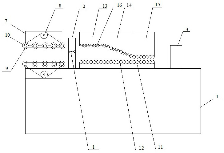
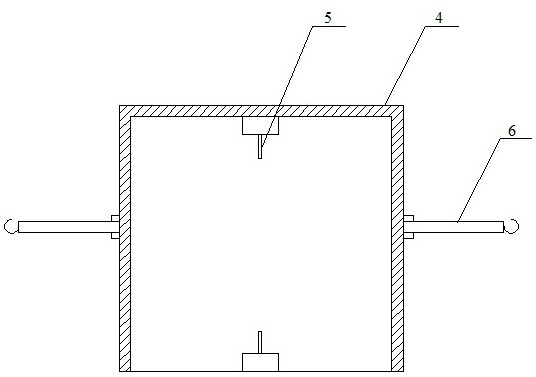
[0030] Such as Figure 1~2 As shown, a cable peeling device for high-voltage cable connection includes a platform 1, a conveying mechanism arranged on the platform 1, a first peeling mechanism 2 for removing the cable sheath, a dispersion mechanism and a The second peeling mechanism 3 for removing the insulation layer of each cable wire; the first peeling mechanism 2 includes a "door" type support 4, a cutter 5 and a pull hook 6, and the "door" type support 4 is arranged on the On the platform 1, the left and right sides of the "door"-shaped bracket are hinged with a drag hook 6, and the upper side of the "door"-shaped bracket 4 and the platform 1 are provided with a cutter 5.
[0031] Specifically, the conveying mechanism includes two conveying modules symmetrically arranged up and down. The conveying module includes a frame body 7, a driving wheel 8 and a plurality of driven wheels 9 arranged on the frame body 7, and a plurality of Gears 10 are arranged on the outer sides o...
Embodiment 2
[0034] Such as Figure 1~3 As shown, a cable peeling device for high-voltage cable connection includes a platform 1, a conveying mechanism arranged on the platform 1, a first peeling mechanism 2 for removing the cable sheath, a dispersion mechanism and a The second peeling mechanism 3 for removing the insulation layer of each cable wire; the first peeling mechanism 2 includes a "door" type support 4, a cutter 5 and a pull hook 6, and the "door" type support 4 is arranged on the On the platform 1, the left and right sides of the "door"-shaped bracket are hinged with a drag hook 6, and the upper side of the "door"-shaped bracket 4 and the platform 1 are provided with a cutter 5.
[0035] Specifically, the conveying mechanism includes two conveying modules symmetrically arranged up and down. The conveying module includes a frame body 7, a driving wheel 8 and a plurality of driven wheels 9 arranged on the frame body 7, and a plurality of Gears 10 are arranged on the outer sides o...
Embodiment 3
[0042] Such as Figure 4~5 As shown, the cable peeling device used for high-voltage cable connection in this embodiment of the present invention is different from Embodiments 1 and 2 in that: each of the risers 11 is provided with a plurality of grooves 26, and the first The two ends of the roller body 12 are respectively located in the groove body 26, the second spring 27 is arranged in the groove body 26, and the baffle plate 28 is arranged on the upper part of the spring 27.
[0043] A plurality of cross bars 29 are arranged on both sides of the second dispersing module, a bearing 30 is connected to both ends of the second roller body 16, a vertical bar 31 is arranged on the upper part of the bearing 30, and a long rod 31 is arranged on the vertical rod 31. The third spring 32 is sheathed on the vertical bar 31 , the horizontal bar 29 is passed through the long hole, and the horizontal bar 29 is located above the third spring 32 .
[0044] In the embodiment of the present ...
PUM
 Abstract
Description
Claims
Application Information
 - Generate Ideas
- Intellectual Property
- Life Sciences
- Materials
- Tech Scout
- Unparalleled Data Quality
- Higher Quality Content
- 60% Fewer Hallucinations
Browse by: Latest US Patents, China's latest patents, Technical Efficacy Thesaurus, Application Domain, Technology Topic, Popular Technical Reports.
© 2025 PatSnap. All rights reserved.Legal|Privacy policy|Modern Slavery Act Transparency Statement|Sitemap|About US| Contact US: help@patsnap.com


