
Evaporation pipe structure for engine combustion chamber, combustion chamber device and preparation method

A technology of evaporating tubes and combustion chambers, which is applied in the direction of combustion methods, combustion chambers, combustion equipment, etc., can solve problems such as inability to meet higher requirements, achieve the effects of reducing the probability of ablation, uniform distribution of oil and gas, and strengthening air turbulence disturbance

Pending Publication Date: 2020-11-13
NAT INST CORP OF ADDITIVE MFG XIAN
View PDF5 Cites 0 Cited by
  • Summary
  • Abstract
  • Description
  • Claims
  • Application Information

AI Technical Summary

Problems solved by technology

[0004] With the increasingly stringent environmental protection indicators, it is necessary for the burner to meet the design requirements of low pollutant emissions; in order to meet the operation of power gas turbines in a wide range of variable working conditions, it is necessary for the burner to be able to burn stably under high and low working conditions, and There is no flameout or oscillation. At present, the combustion chamber of the micro-turbojet engine cannot meet the higher requirements of combustion performance. Considering the comprehensive performance requirements of the entire combustion chamber, it is necessary to balance the size distribution characteristics of the liquid mist, which requires detailed analysis of the evaporation tube structure. Design and manufacture to meet the requirements of use

Method used


Image

  • Evaporation pipe structure for engine combustion chamber, combustion chamber device and preparation method
  • Evaporation pipe structure for engine combustion chamber, combustion chamber device and preparation method
  • Evaporation pipe structure for engine combustion chamber, combustion chamber device and preparation method

Examples


Embodiment Construction

[0045] The present invention is described in further detail below in conjunction with accompanying drawing:

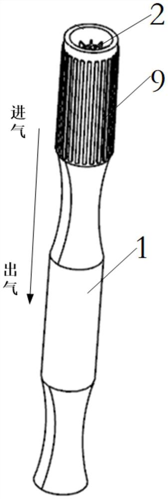
[0046] Such as Figure 1 to Figure 4 As shown, an evaporator tube structure for an engine combustion chamber includes an evaporator tube body 1, and the evaporator tube body 1 includes a first cylindrical section, a concave curved surface section, a second cylindrical section, and an outlet in sequence from the air inlet end to the air outlet end. section; the first cylindrical section is provided with a first double cyclone 2 whose axis is parallel to the axis of the evaporation tube body 1, and the second cylindrical section is provided with a second double cyclone whose axis is parallel to the axis of the evaporation tube body 1 device 3 and the third double cyclone 4, the second double cyclone 3 and the third double cyclone 4 are arranged at intervals along the axial direction of the evaporation tube body 1, such as Figure 9 As shown, the blades of two adjacent d...


PUM


Abstract

The invention discloses an evaporation pipe structure for an engine combustion chamber, a combustion chamber device and a preparation method. An evaporation pipe body of the evaporation pipe structureis arranged in an evaporation pipe combustion chamber of a double-layer combustion chamber body, the air inlet end of the evaporation pipe body makes contact with the inner wall of the rear end of the double-layer combustion chamber body, and a rear cover oil inlet hole communicated with the evaporation pipe body is formed in the inner wall of the rear end of the double-layer combustion chamber body; and the air outlet end of the evaporation pipe body is located in the evaporation pipe combustion chamber of the double-layer combustion chamber body, the inner walls of the front end of the double-layer combustion chamber body are arranged at intervals, the included angle between the axis of the evaporation pipe body and the axis of the double-layer combustion chamber body is 15-25 degrees,evaporation pipe bodies are evenly arranged in the circumferential direction of the inner wall of the rear end of a combustion chamber flame tube of the double-layer combustion chamber body and form an angle with the axis of the flame tube, a fuel nozzle is inserted into the evaporation pipe along a certain angle and forms reverse injection with incoming air, and stable, efficient and ultralow-pollution combustion is achieved through the high-temperature and low-oxygen condition in a high-temperature fuel gas backflow area.

Description

technical field [0001] The invention belongs to the field of engine combustion systems, and in particular relates to an evaporation tube structure for an engine combustion chamber, a combustion chamber device and a preparation method. Background technique [0002] Modern high-performance aeroengines require an increase in turbine inlet temperature to increase unit thrust. Combustion chamber component design technology will develop towards high temperature rise and high heat capacity combustion. With the rise of the combustion chamber, the total oil-gas ratio of the combustion chamber increases, requiring the combustion chamber to work in a wider range of oil-gas ratio. If the oil-gas ratio is increased a lot, serious smoke will be generated. If the gas volume is increased, it will be difficult to ignite and stabilize the flame. This is solved by improving the airflow organization in the combustion chamber head, fuel atomization and air premixing. The high-performance comb...

Claims


Application Information

Patent Timeline
Patent Type & Authority Applications(China)
IPC IPC(8): F02C7/18F02C7/00F23R3/28F23R3/32
CPCF02C7/00F02C7/18F23R3/286F23R3/32
Inventor 眭晓蔚卢秉恒张琦代赟
Owner NAT INST CORP OF ADDITIVE MFG XIAN
Learn More