Flue gas collaborative purification system and flue gas collaborative purification method

A purification system and flue gas technology, applied in chemical instruments and methods, separation methods, gas treatment, etc., can solve problems such as high cost, complicated control methods, and limited improvement of problems

Pending Publication Date: 2020-11-13
FUJIAN LONGKING
View PDF5 Cites 0 Cited by
  • Summary
  • Abstract
  • Description
  • Claims
  • Application Information

AI Technical Summary

Problems solved by technology

[0004] Existing technology for NH-based 3 NH 4 HSO 4 There are various control methods, such as by monitoring its NH 3 and SO 3 Concentration to condition the flue gas, or control the amount of ammonia injection, etc., the control method is more complicated, the cost is higher, NH 3 The problem improvement effect caused by escape is also limited

Method used


Image

  • Flue gas collaborative purification system and flue gas collaborative purification method
  • Flue gas collaborative purification system and flue gas collaborative purification method

Examples


Embodiment Construction

[0037] In order to enable those skilled in the art to better understand the technical solutions of the present invention, the present invention will be further described in detail below in conjunction with the accompanying drawings and specific embodiments.

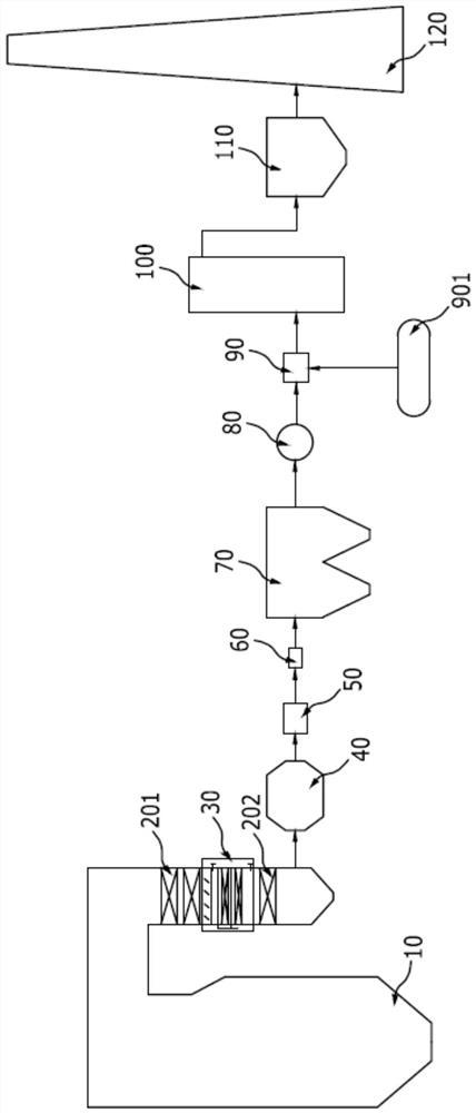
[0038] Such as figure 1 as shown, figure 1 It is a structural schematic diagram of a specific embodiment of the flue gas collaborative purification system provided by the present invention.

[0039] The flue gas synergistic purification system in this embodiment communicates with the boiler 10, and the flue gas in the boiler 10 flows to the flue gas synergistic purification system. The flue gas synergistic purification system specifically includes a catalytic oxidation zone 30 arranged along the flue gas flow direction, an ozone oxidation The reaction zone 90 and the desulfurization and denitrification zone.

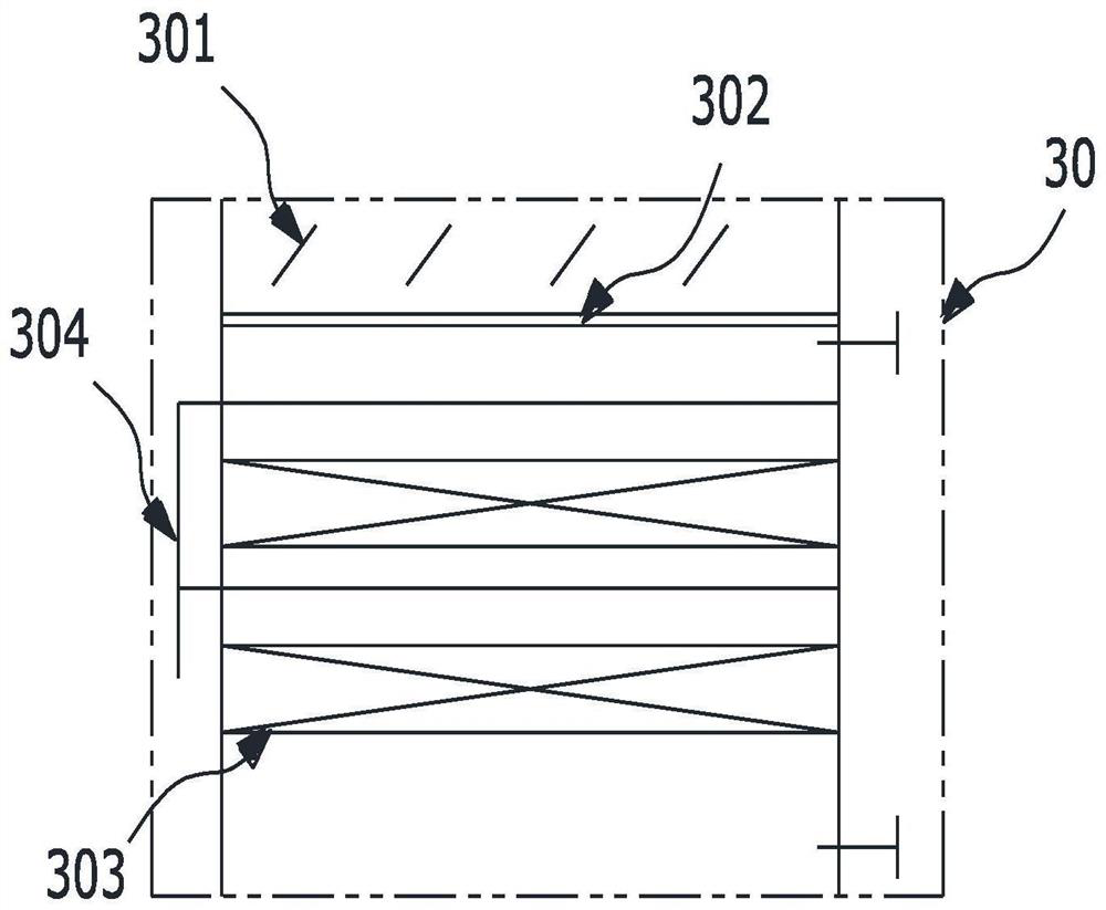
[0040] Wherein, catalytic oxidation zone 30 can refer to figure 2 understand, figure 2 for figure 1 An enl...


PUM


Abstract

The invention discloses a flue gas collaborative purification system and a flue gas collaborative purification method. The flue gas collaborative purification system comprises a catalytic oxidation area, a dust removal area, an ozone oxidation reaction area and a desulfurization and denitrification area which are arranged along the flow direction of flue gas, the catalytic oxidation area is provided with a catalytic oxidation catalyst module; sulfur dioxide is oxidized into sulfur trioxide in the catalytic oxidation area and is combined with water vapor to form sulfuric acid mist, and the sulfuric acid mist is removed in the dust removal area; the ozone oxidation reaction area is used for further oxidizing nitric oxide, and the desulfurization and denitrification area is provided with an alkaline removing agent. According to the scheme, through cooperation of the catalytic oxidation area, the dust removal area, the ozone oxidation reaction area and the desulfurization and denitrification area, the effect of synergistic removal of denitrification, dust removal and desulfurization can be well achieved.

Description

technical field [0001] The invention relates to the technical field of flue gas treatment, in particular to a flue gas collaborative purification system and a flue gas collaborative purification method. Background technique [0002] At present, in order to meet the emission standards of gas pollutants, the desulfurization and denitrification methods for purifying flue gas are mainly the combination of SNCR / SCR denitrification and wet desulfurization. [0003] Among them, SCR can stabilize NO X emission, SCR mainly injects ammonia reducing agent (NH 3 ), under the action of a catalyst, a reduction reaction occurs with nitrogen oxides, so as to achieve the purpose of removing nitrogen oxides. However, due to problems such as changes in boiler load, difficulty in controlling the amount and uniformity of ammonia injection, and uncertainty in the degree of reaction, ammonia slip will inevitably occur. The escaped NH3 catalyzes the oxidation of SO with the catalyst 2 converted...

Claims


Application Information

Patent Timeline
IPC IPC(8): B01D53/86B01D53/78B01D53/76B01D53/60B01D53/56B01D50/00
CPCB01D53/8637B01D53/56B01D53/76B01D50/00B01D53/78B01D53/60B01D2251/104B01D2258/0283Y02A50/20
Inventor 李永丰李俊霖曾艳陈奎续左鹏马晓辉王永桥
Owner FUJIAN LONGKING
Why Eureka
Try Eureka