A flooded chiller

A chiller, flooded technology, applied in refrigerators, refrigeration components, compressors, etc., can solve the problems of many fault points, many connection points, and high manufacturing costs, and achieve convenient maintenance, solve system blockage, and refrigeration effect. Good results

Inactive Publication Date: 2015-10-21
DONGGUAN XINTAO MACHINERY
View PDF3 Cites 0 Cited by
  • Summary
  • Abstract
  • Description
  • Claims
  • Application Information

AI Technical Summary

Problems solved by technology

[0002] Traditional flooded chillers cannot effectively solve compressor oil return, high manufacturing cost and complicated process, resulting in: 1. Traditional flooded chillers only have large central air-conditioning units in China and cannot be used in small units 2. In the traditional flooded chiller system, the refrigerant in the evaporator goes through the shell side, and the chilled water goes through the tube side, which results in excessive refrigerant charge in the system. If leakage occurs, the refrigerant will pollute the environment and cause damage to the atmosphere , or if water enters the shell side, the compressor will be damaged after the compressor absorbs water; 3. The traditional flooded type oil separator is added between the compressor exhaust port and the condenser, which will cause oil separation during long-term use. The oil separator cannot completely separate the oil, resulting in long-term accumulation in the shell side of the evaporator. When the oil return is not urgent, the compressor is damaged or burned out due to the lack of oil; 4. In order to solve the oil return of the compressor, many units use ejectors Pump and solenoid valve control, but because the cost of ejector pump is relatively high and the process is relatively complicated, so there are many connection points, resulting in many failure points, causing leakage during post-manufacturing and transportation, and bringing serious economic losses to the manufacturer. loss

Method used


Image

  • A flooded chiller
  • A flooded chiller

Examples


Embodiment Construction

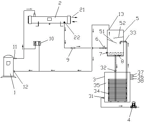
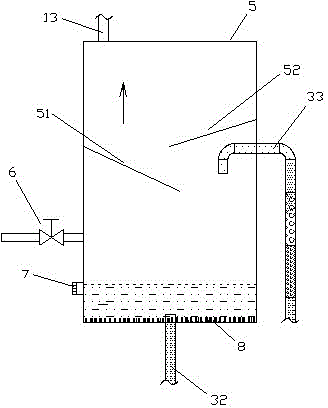
[0016] refer to figure 1 , figure 2 , a flooded water chiller of the present invention, comprising a gas compressor 1, a condenser 2 connected to the gas outlet 11 of the gas compressor 1, an outlet 22 of the condenser 2 and an inlet 12 of the gas compressor 1 The connected heat exchanger 3, the end of the condenser 2 is provided with a cooling water inlet and outlet 21, the bottom water outlet 31 of the heat exchanger 3 is connected with a water pump 4, and the outlet 22 of the condenser 2 and the gas compressor The inlet end 12 of 1 is communicated with heat exchanger 3 respectively and also communicates with a vapor-liquid separation device 5 in the middle, and described vapor-liquid separation device 5 is connected with the outlet 22 of condenser 2 and the inlet end of gas compressor 1 respectively. 12. The liquid inlet 32 ​​and the gas outlet 33 of the heat exchanger 3 are connected to each other, and a throttling device 6 is provided between the outlet 22 of the co...


PUM


Abstract

The invention discloses a hydraulic-filling-type water chilling unit which comprises a gas compressor, a condenser and a heat exchanger, wherein the condenser is communicated with the gas outlet end of the gas compressor, the heat exchanger is communicated with a discharge port of the condenser and the gas inlet end of the gas compressor, a cooling water inlet and outlet is arranged at the end part of the condenser, and a water outlet of the bottom of the heat exchanger is communicated with a water pump. The middle part where the discharge port of the condenser and the gas inlet end of the gas compressor are respectively communicated with the heat exchanger is communicated with a gas-liquid separation device. The discharge port of the condenser, the gas inlet end of the gas compressor, a liquid inlet of the heat exchanger, and a gas outlet of the heat exchanger are respectively communicated with the gas-liquid separation device in a butt-joint mode. A throttling device is arranged between the discharge port of the condenser and the gas-liquid separation device. The hydraulic-filling-type water chilling unit has the advantages of being large in refrigerating capacity, good in refrigerating effect, good in oil return effect, cost-saving, convenient to operate, and convenient to maintain due to the fact the system cannot be easily blocked.

Description

technical field [0001] The invention relates to a refrigeration device, in particular to a flooded water chiller. Background technique [0002] Traditional flooded chillers cannot effectively solve compressor oil return, high manufacturing cost and complicated process, resulting in: 1. Traditional flooded chillers only have large central air-conditioning units in China and cannot be used in small units 2. In the traditional flooded chiller system, the refrigerant in the evaporator goes through the shell side, and the chilled water goes through the tube side, which results in excessive refrigerant charge in the system. If leakage occurs, the refrigerant will pollute the environment and cause damage to the atmosphere , or if water enters the shell side, the compressor will be damaged after the compressor absorbs water; 3. The traditional flooded type oil separator is added between the compressor exhaust port and the condenser, which will cause oil separation during long-term u...

Claims


Application Information

Patent Timeline
Patent Type & Authority Patents(China)
IPC IPC(8): F25B1/00F25B31/00
Inventor 黄愈淞
Owner DONGGUAN XINTAO MACHINERY
Why Eureka
Try Eureka