
Composite heat dissipation device adopting composite phase change materials and micro-channel liquid cooling

A technology of composite phase change material and heat dissipation device, applied in the field of heat dissipation device, can solve the problems of unsatisfactory heat dissipation effect, poor heat dissipation effect, affecting the service life of LED, etc., and achieves the effects of compact structure, improved lubrication conditions, and improved heat dissipation effect.

Pending Publication Date: 2020-11-10
UNIV OF ELECTRONICS SCI & TECH OF CHINA
View PDF9 Cites 5 Cited by
  • Summary
  • Abstract
  • Description
  • Claims
  • Application Information

AI Technical Summary

Problems solved by technology

The heat dissipation effect is not ideal. If it encounters an external hot and high temperature environment, the heat dissipation effect will be even worse, which will directly affect the service life of the LED

Method used


Image

  • Composite heat dissipation device adopting composite phase change materials and micro-channel liquid cooling
  • Composite heat dissipation device adopting composite phase change materials and micro-channel liquid cooling
  • Composite heat dissipation device adopting composite phase change materials and micro-channel liquid cooling

Examples


Embodiment 1

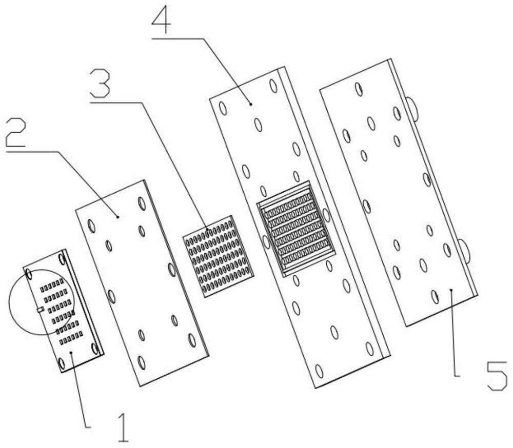
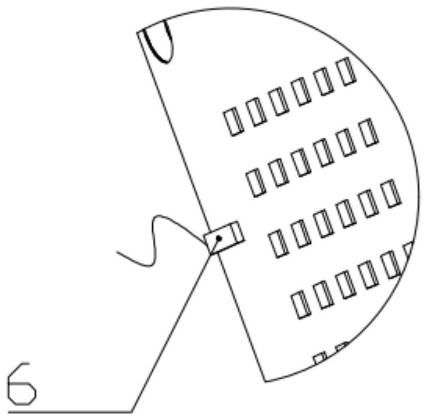
[0040] A composite heat dissipation device using composite phase change material and microchannel liquid cooling, including LED light source module 1, phase change zone cover plate 2, paraffin-graphene composite phase change material 3, radiator 4, and liquid cooling zone cover plate 5 , Temperature sensor 6, controller, water pump, cooling water tank, external S-shaped cooling pipe. The heat generated by the LED light source module 1 is transferred to the microchannel liquid cooling area through the paraffin-graphene latent heat release area 41, and the graphene cooling liquid flows into the radiator 4, flows in from the liquid injection port 51, and flows out from the liquid outlet 52, completing a round Heat dissipation.

[0041] Among them, the length and width of the central main flow channel are 38mm*5mm; the widest part of the spoiler column is 1mm, the length is 20mm, and the overall shape is arc-shaped; the length and width of the first-stage flow channel are 28mm*2mm...

Embodiment 2

[0046] On the basis of Embodiment 1, the speed of the water pump can be adjusted in real time through the temperature sensor 6 and the controller, which can reduce power loss, achieve optimal heat dissipation, save costs to the greatest extent, and prolong the service life of the entire system. At the same time, the structures of the paraffin latent heat release zone 41 and the microchannel liquid cooling zone can be optimized according to the requirements of different LED heat source densities, such as adjusting the density distribution of foamed aluminum, the mass fraction of graphene, and the paraffin-graphene latent heat release The volume size of the area, the width distribution of the microchannel, etc., to achieve the best heat dissipation effect.


PUM


Abstract

The invention discloses a composite heat dissipation device adopting composite phase change materials and micro-channel liquid cooling, relates to the field of cold heat dissipation, in particular tothe heat dissipation device adopting combination of the phase change materials and the liquid cooling. The heat dissipation device comprises a phase change area cover plate, the phase change materials, a radiator and a liquid cooling area cover plate; the radiator is of a plate-shaped structure, a concave area for containing the phase change materials is formed in one side of the radiator, and a micro-channel is formed in the other side corresponding to the concave area; the phase change materials are packaged by the phase change area cover plate, the micro-channel is packaged by the liquid cooling area cover plate, and a liquid injection port and a liquid outlet of cooling liquid are formed in one side, which is not packaged, of the liquid cooling area cover plate; and the heat source isarranged on the unpackaged side of the phase change area cover plate. The composite heat dissipation device is characterized in that a plurality of columnar protrusions made of foamed aluminum materials are arranged in the concave area of the radiator in an array mode, gaps among the columnar protrusions in the concave area are filled with the phase change materials, and a circle of sealing grooveis formed in the outer side of the concave area. The composite heat dissipation device has the advantages of uniform heat dissipation and high heat dissipation efficiency.

Description

technical field [0001] The invention relates to the field of cooling and heat dissipation, in particular to a heat dissipation device combining phase change materials and liquid cooling. Background technique [0002] LED (Light Emitting Diode), light-emitting diode, is a solid-state semiconductor device that can directly convert electricity into light. With the gradual maturity of LED technology, its advantages such as energy saving, low cost, long life, good durability, small component size, fast response speed, and low brightness attenuation have begun to attract attention. Therefore, the application of LED lamps in various industries is becoming more and more extensive. At present, LEDs are widely used in street lighting, wharf lighting, mine lighting and other places that require high light efficiency. [0003] With the reduction in size, the substantial increase in power, and the limitation of current processing technology, when the LED light source is in working cond...

Claims


Application Information

Patent Timeline
IPC IPC(8): F21V29/56F21V29/57F21V29/51H01L33/64F21Y115/10
CPCF21V29/56F21V29/57F21V29/51H01L33/641H01L33/648F21Y2115/10
Inventor 徐尚龙周川翔徐冲
Owner UNIV OF ELECTRONICS SCI & TECH OF CHINA
Learn More