A kind of semiconductor die with sealing ring structure and its preparation method
A technology of semiconductor tubes and sealing rings, applied in semiconductor devices, semiconductor/solid-state device parts, electric solid-state devices, etc., to achieve excellent water vapor resistance and eliminate cutting stress
- Summary
- Abstract
- Description
- Claims
- Application Information
AI Technical Summary
Problems solved by technology
Method used
Image
Examples
preparation example Construction
[0031] This embodiment provides a method for preparing a semiconductor die with a sealing ring structure, comprising the following steps:
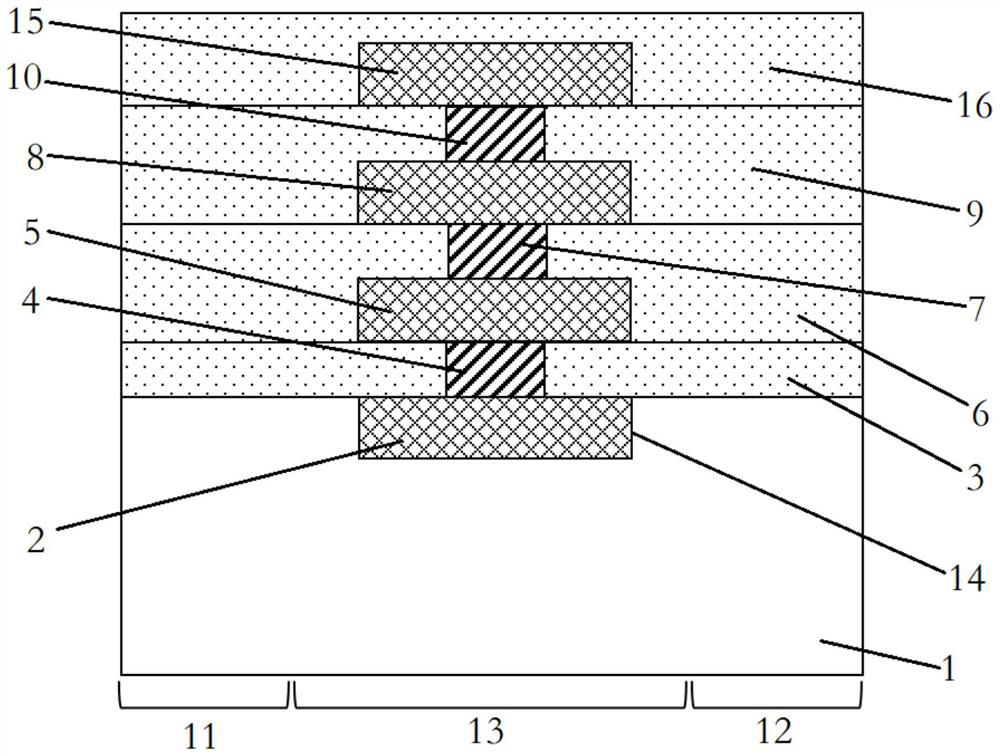
[0032] Such as figure 1 As shown, 1) a semiconductor wafer 1 is provided, and the semiconductor wafer 1 includes a dicing area 11, an integrated circuit area 12 and a seal ring area 13 between the dicing area 11 and the integrated circuit area 12. A trench 14 is formed in the sealing ring region 13 of the semiconductor wafer 1 .
[0033] Wherein, the semiconductor wafer 1 can specifically be a silicon substrate, a germanium substrate, a silicon germanium substrate or an SOI substrate, and the integrated circuit region 12 has devices such as field effect transistors, resistors, capacitors, inductors, and diodes, and the trench 14 Formed by wet etching or dry etching, the depth of the trench 14 is 800-2500 nanometers.
[0034] In a specific embodiment, a photoresist is coated on the semiconductor wafer 1, and a mask with an exposed part of...
Embodiment 1
[0062] Implementation 1: A method for preparing a semiconductor die with a sealing ring structure, comprising the following steps:
[0063] 1) A semiconductor wafer is provided, the semiconductor wafer includes a dicing area, an integrated circuit area, and a sealing ring area between the dicing area and the integrated circuit area, and the sealing ring of the semiconductor wafer is A trench is formed in the region.
[0064]2) Next, a mask is formed on the semiconductor wafer, and the mask only exposes the region where the groove is located, and then a solution containing metal nanoparticles is spin-coated on the semiconductor wafer to form a layer in the groove. A first metal nanoparticle layer is formed in the groove, and then the mask is removed.
[0065] 3) Then forming a first dielectric layer on the semiconductor wafer, and then forming a plurality of first through holes on the first dielectric layer, the plurality of first through holes are arranged at intervals and ex...
Embodiment 2
[0072] Implementation 2: In the step 1), the trench is formed by wet etching or dry etching, and the depth of the trench is 800-2500 nanometers.
PUM
| Property | Measurement | Unit |
|---|---|---|
| depth | aaaaa | aaaaa |
| particle diameter | aaaaa | aaaaa |
| particle diameter | aaaaa | aaaaa |
Abstract
Description
Claims
Application Information
 - R&D
- Intellectual Property
- Life Sciences
- Materials
- Tech Scout
- Unparalleled Data Quality
- Higher Quality Content
- 60% Fewer Hallucinations
Browse by: Latest US Patents, China's latest patents, Technical Efficacy Thesaurus, Application Domain, Technology Topic, Popular Technical Reports.
© 2025 PatSnap. All rights reserved.Legal|Privacy policy|Modern Slavery Act Transparency Statement|Sitemap|About US| Contact US: help@patsnap.com

