A quick opening stop valve
A technology of stop valve and bonnet, which is applied in the direction of lifting valve, valve device, valve details, etc. It can solve the problems of large torque, difficulty in fast opening and closing, and inability to open the stop valve in time, so as to achieve the effect of protecting work safety
Active Publication Date: 2022-05-31
乐清市东风煤矿设备有限公司
View PDF9 Cites 0 Cited by
- Summary
- Abstract
- Description
- Claims
- Application Information
AI Technical Summary
Problems solved by technology
[0003] In view of the related technologies mentioned above, the inventor believes that there are: when the shut-off valve is opened and closed, the torque is large, and it is difficult to realize rapid opening and closing. When the medium in the hydraulic pipeline needs to pass through the shut-off valve quickly, the shut-off valve cannot be opened in time, which is difficult to deal with. emergency
Method used
View moreImage
Smart ImageViewing Examples
Examples
Embodiment Construction
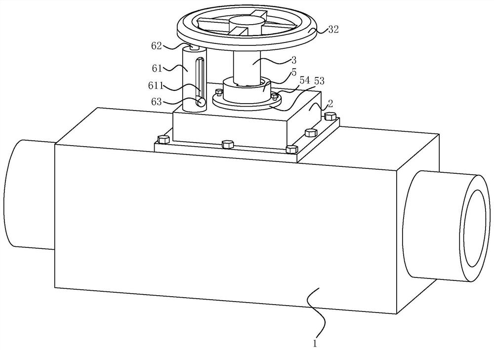
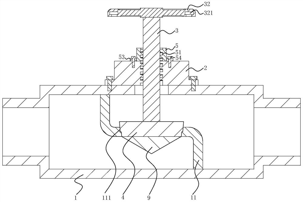
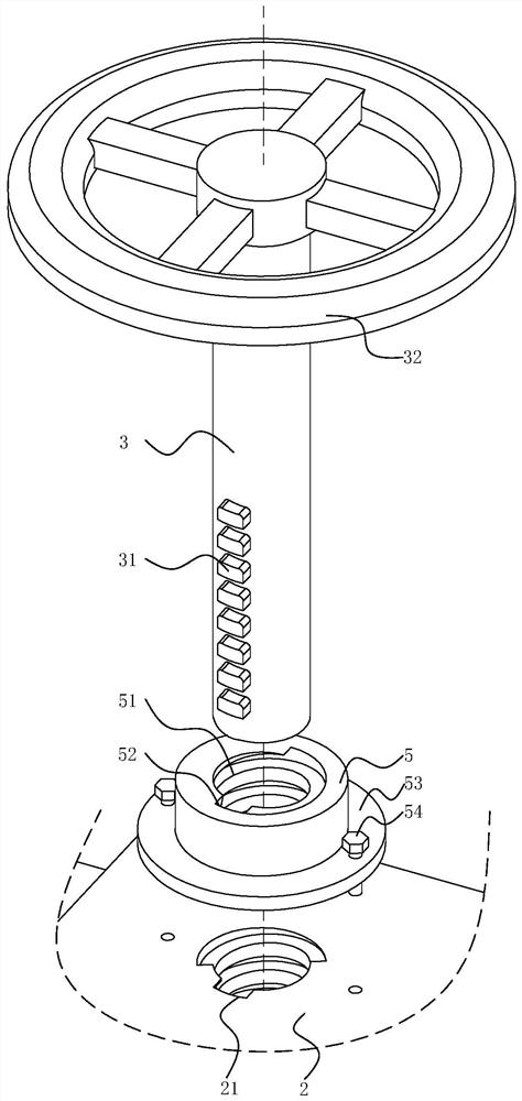
[0038] The embodiment of the present application discloses a quick-opening stop valve.
Login to View More PUM
 Abstract
This application relates to a quick-opening stop valve, which includes a valve body, a valve cover, a valve stem and a valve disc. A partition plate is fixed inside the valve body. There is a through groove on the plate, the valve stem runs through the bonnet and is threadedly connected with the bonnet. Open along the length direction of the bonnet and set parallel to the central axis of the bonnet, the break-off channel interrupts the internal threads of the bonnet in sequence, multiple sliders are fixed on the outer wall of the valve stem, and adjacent sliders are arranged along the length direction of the valve stem , the connecting line of the adjacent sliders is parallel to the breaking channel, the central axis of the valve stem and the bonnet is in line, the valve stem rotates on its own axis, and the sliding block is adapted to slide relative to the inner thread of the bonnet itself; the slider rotates to the breaking channel , can slide along the length of the breaking channel. The application has the effect of quickly opening the shut-off valve to deal with emergencies.
Description
A quick-opening stop valve technical field [0001] The application relates to the field of valves, in particular to a quick-opening shut-off valve. Background technique At present, the cut-off valve is also called the cut-off valve, which belongs to the forced sealing valve, so when the valve is closed, it must be applied to the valve disc. Apply pressure to force the sealing faces to not leak. The opening and closing part of the globe valve is a plug-shaped disc, and the disc is straight along the center line of the valve seat. sports. The valve stem adopts the lifting and rotating rod type, which can be used to control air, water, steam, mud, oil, liquid metal and radioactive medium. Therefore, this type of shut-off valve is very suitable for cutting, regulating and throttling. Depend on The opening or closing stroke of the valve stem of this type of valve is relatively short, and it has a very reliable shut-off function. The change of the port is proportional ...
Claims
Login to View More Application Information
Patent Timeline
 Patent Type & Authority Patents(China)
IPC IPC(8): F16K1/02F16K1/32F16K1/38F16K27/02F16K31/60F16K31/50F16K47/00F16P1/00
CPCF16K1/02F16K1/32F16K1/38F16K27/0254F16K31/60F16K31/50F16K47/00F16P1/00
Inventor 陈定余陈永乐李学州唐大春
Owner 乐清市东风煤矿设备有限公司
Features
- R&D
- Intellectual Property
- Life Sciences
- Materials
- Tech Scout
- Unparalleled Data Quality
- Higher Quality Content
- 60% Fewer Hallucinations
Learn More Browse by: Latest US Patents, China's latest patents, Technical Efficacy Thesaurus, Application Domain, Technology Topic, Popular Technical Reports.
© 2025 PatSnap. All rights reserved.Legal|Privacy policy|Modern Slavery Act Transparency Statement|Sitemap|About US| Contact US: help@patsnap.com


