Gas production device of high-gas-content well

A technology for gas production and gas wells, which is applied in the field of gas production devices and wellhead devices for high gas content wells, and can solve problems such as idle resources, lower temperature of produced fluid, and easy freezing of nozzle sleeves, etc.

Active Publication Date: 2020-11-06
CHINA PETROLEUM & CHEM CORP +1
View PDF23 Cites 1 Cited by
  • Summary
  • Abstract
  • Description
  • Claims
  • Application Information

AI Technical Summary

Problems solved by technology

[0003] At present, oil nozzles with different apertures are usually installed in the nozzle sleeves to control the production when the water content is very low in the initial stage of oil injection wells in the oil field. Thick, wax deposits on the nozzle sleeve, partially or completely clogs the nozzle, reduces crude oil production, and may cause well operation in severe cases
At present, the main method to solve this problem on site is that the staff use a nozzle wrench to remove the plug, then remove the nozzle to clean it, and then reinstall it. Wax freezing
[0004] In addition, the casing gas pressure of high gas-bearing wells can be as high as 10MPa, which is much higher than the gas pressure in the tubing. Due to the huge throttling pressure difference, the nozzle sleeve is more likely to freeze and block and cannot operate normally.
The decompression skid can only be used to depressurize and absorb gas. On the one hand, it will increase the production cost. On the other hand, the decompression skid needs to be supplied with hot water stations. If there is no hot water station on site, a large amount of casing gas cannot output, resulting in idle resources, or even waste

Method used


Image

  • Gas production device of high-gas-content well
  • Gas production device of high-gas-content well
  • Gas production device of high-gas-content well

Examples


Embodiment Construction

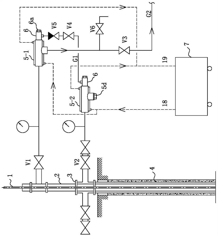
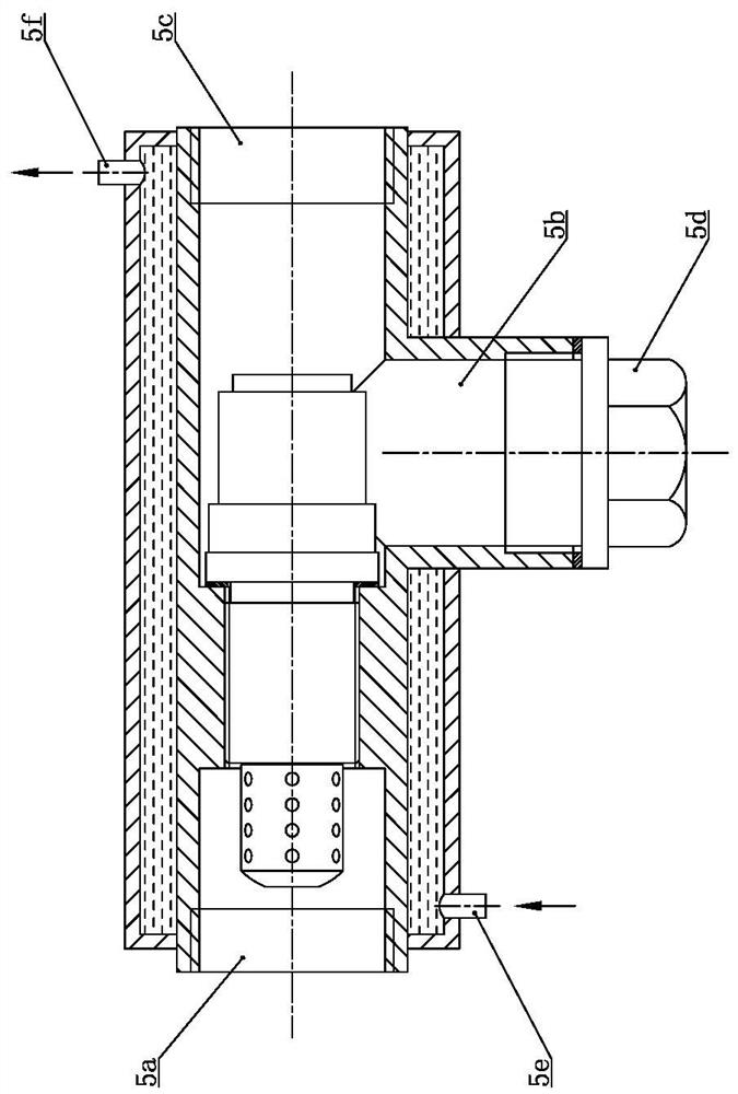
[0033] Such as figure 1 , figure 2 As shown, in the gas production device of the high gas content well of the present invention, the sucker rod 1 extends downhole along the oil pipe 2 from top to bottom, the oil pipe 2 is located in the downhole casing 4, and the upper port of the downhole casing 4 is installed with a The above wellhead spool 3, the upper end of the tubing 2 passes through the center of the wellhead spool 3, the left and right sides of the wellhead spool 3 are respectively connected with the casing gate V2 communicating with the downhole casing annulus, the upper part of the tubing 2 One side is connected with the production gate V1, the outlet of the production gate V1 is connected with the high-pressure inlet 5a of the nozzle sleeve 1 5-1, and the middle low-pressure outlet 5b of the nozzle sleeve 5-1 is connected to the underground gathering and transportation main pipe G2 through the back pressure valve V3 Connected; the upstream of the back pressure val...


PUM


Abstract

The invention relates to a gas production device of a high-gas-content well. A sucker rod extends to the underground along an oil pipe, the oil pipe is located in an underground casing pipe, an upperport of the underground casing pipe is provided with a wellhead four-way located above the ground, the upper end of the oil pipe penetrates through the center of the wellhead four-way, left and rightsides of the wellhead four-way are respectively connected with a casing gate communicated with an annular space of the underground casing pipe, one side of the upper part of the oil pipe is connectedwith a production gate, an outlet of the production gate is connected with a high-pressure inlet of a first oil nozzle sleeve, a middle low-pressure outlet of the first oil nozzle sleeve is connectedwith an underground gathering and conveying main pipe through a back-pressure valve, an outlet of the casing gate on one side is connected with a high-pressure inlet of a second nozzle sleeve, a sealing plug is installed at a middle low-pressure outlet of the second nozzle sleeve, a low-pressure overhaul port of the second nozzle sleeve is connected with a low-pressure overhaul port of the first nozzle sleeve through a connecting pipe, and a needle valve and a check valve are connected in series in the connecting pipe. According to the device, the oil pipe gas and the casing pipe gas can bothbe collected into the gathering and conveying main pipe, the yield is greatly improved, and continuous and stable production can be realized.

Description

technical field [0001] The invention relates to a wellhead device, in particular to a gas recovery device for a high gas content well, and belongs to the technical field of oil and gas well site devices. Background technique [0002] The nozzle sleeve is an essential accessory in the production of the petroleum industry. It is used together with the Christmas tree. It is usually installed at the tee of the Christmas tree at the wellhead to control oil pressure and oil output. The traditional nozzle cover includes a nozzle cover tee. One end of the oil nozzle cover tee is a high-pressure oil inlet, and the other end of the oil nozzle cover tee is a low-pressure inspection port. There is a nozzle seat between the low-pressure oil outlet, the high-pressure oil inlet and the middle outlet, and a nozzle is screwed into the nozzle seat, and the throat hole in the middle of the center hole of the nozzle controls oil pressure and flow. [0003] At present, oil nozzles with differen...

Claims


Application Information

Patent Timeline
Patent Type & Authority Applications(China)
IPC IPC(8): E21B43/00E21B34/02F17D1/02F16L53/32
CPCE21B43/00E21B34/02F17D1/02F16L53/32
Inventor 付江徽杨莲周彦杰陈苏海张宏田斌郑静
Owner CHINA PETROLEUM & CHEM CORP
Why Eureka
Try Eureka