Floor heating system
A floor heating and floor heating technology, applied in the field of floor heating, can solve the problems of high professional requirements for construction personnel, complexity, long construction period of wet floor heating, etc., and achieve excellent compressive and bending performance, less materials and light weight.
- Summary
- Abstract
- Description
- Claims
- Application Information
AI Technical Summary
Problems solved by technology
Method used
Image

Examples
Embodiment 1
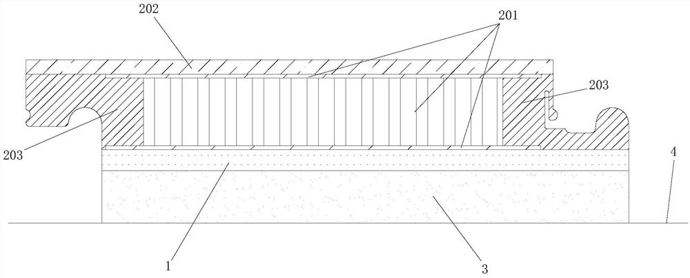
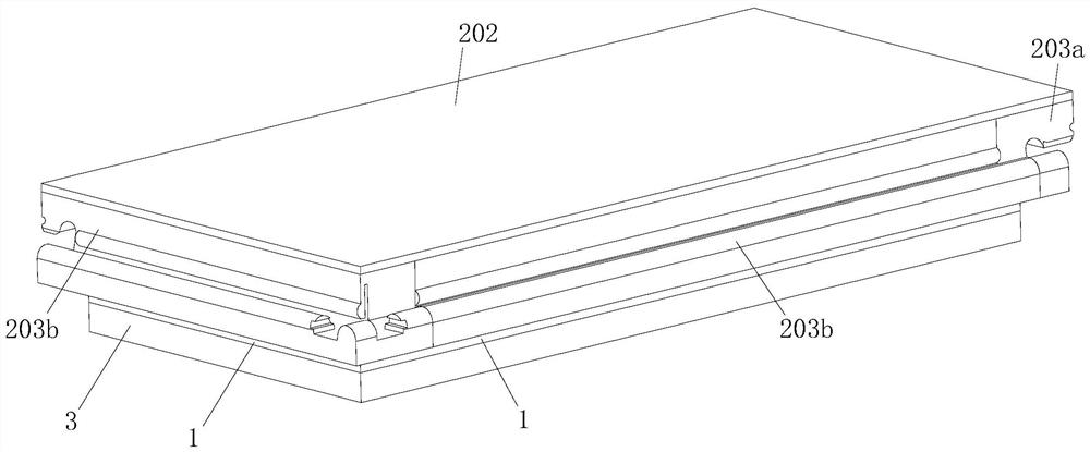
[0061] Figure 1 to Figure 5 A preferred embodiment of the floor heating system of the present application is shown. The floor heating system is an electric heating structure, which includes an electric heating film 1 that generates electricity and a plurality of floor boards 2 above the electric heating film. The electrothermal film 1 can be directly purchased in the market, and is mainly composed of a heating wire and an insulating film encapsulating the aforementioned heating wire. The electric heating film 1 is spread on the ground 4 (generally the indoor ground, including the floor surface), and the floor board 2 is spread on the upper surface of the electric heating film 1 . "The electrothermal film 1 is laid on the ground 4" does not mean that the electrothermal film 1 must be in direct contact with the ground 4.
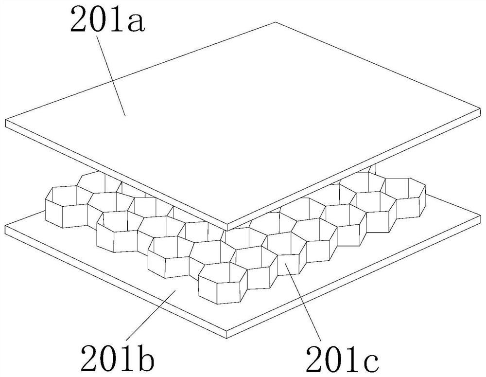
[0062] Each floor board 2 is composed of a metal honeycomb panel 201 , a panel 202 attached to and fixed on the upper surface of the metal honeycomb panel, ...
Embodiment 2
[0084] refer to Figure 6 to Figure 10 As shown, the structure of the floor heating system of this embodiment is basically the same as that of Embodiment 1. The main difference is that the honeycomb core layer 201c of the metal honeycomb panel 201 in this embodiment adopts another structure, thereby improving the structure of the honeycomb core layer 201c and the upper plate. The bonding area and bonding strength of the body 201a and the lower plate body 201b reduce the possibility of the upper and lower plate bodies detaching from the honeycomb core layer as follows:
[0085] The honeycomb core layer 201c is composed of a very thin metal sheet 201c1 and a plurality of downwardly protruding punching protrusions 201c2 that are integrally formed on the metal sheet by punching the metal sheet. The upper surface 201c1a of the metal sheet 201c1 is attached to (the lower surface of) the upper plate body 201a and bonded and fixed, and the lower surface 201c2a of the stamping protrusi...
Embodiment 3
[0094] Figure 11 with Figure 12 Another specific embodiment of the floorboard of the present application is shown, the structure of the floorboard is basically the same as that of the second embodiment, the only difference is that the outer contour of each punching protrusion 201c2 in the honeycomb core layer is cylindrical.
[0095] Apparently, the stamped protrusion 201c2 may also be in other shapes, such as a polygonal column shape.
[0096] However, it is better to set the stamping protrusion 201c2 in the shape of a ring column in the second embodiment, so that the number of vertical support arms between the upper and lower panels can be increased, thereby increasing the compressive strength of the honeycomb panel.
PUM
| Property | Measurement | Unit |
|---|---|---|
| thickness | aaaaa | aaaaa |
Abstract
Description
Claims
Application Information
 - R&D
- Intellectual Property
- Life Sciences
- Materials
- Tech Scout
- Unparalleled Data Quality
- Higher Quality Content
- 60% Fewer Hallucinations
Browse by: Latest US Patents, China's latest patents, Technical Efficacy Thesaurus, Application Domain, Technology Topic, Popular Technical Reports.
© 2025 PatSnap. All rights reserved.Legal|Privacy policy|Modern Slavery Act Transparency Statement|Sitemap|About US| Contact US: help@patsnap.com