Radiant floor heating structure
A floor heating and floor heating pipe technology, applied in building structure, hot water central heating system, heating method, etc., can solve the problems of high professional requirements of construction personnel, complicated, long construction period of wet floor heating, etc., and achieve excellent compressive performance. and bending resistance, less material and lighter weight
- Summary
- Abstract
- Description
- Claims
- Application Information
AI Technical Summary
Problems solved by technology
Method used
Image

Examples
Embodiment 1
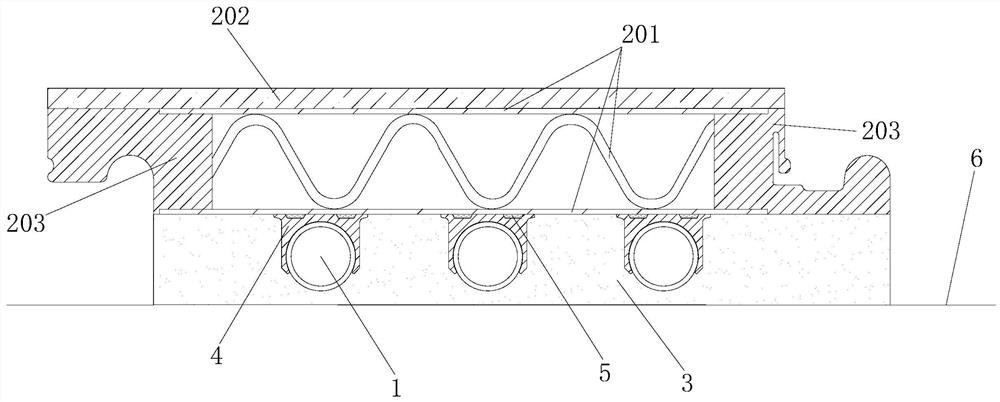
[0055] Figure 1 to Figure 4 A preferred embodiment of the floor heating structure of the present application is shown, which includes a floor heating pipe 1 for running hot water and a plurality of floor boards 2 above the floor heating pipe.
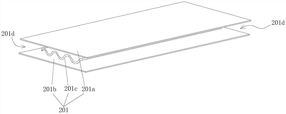
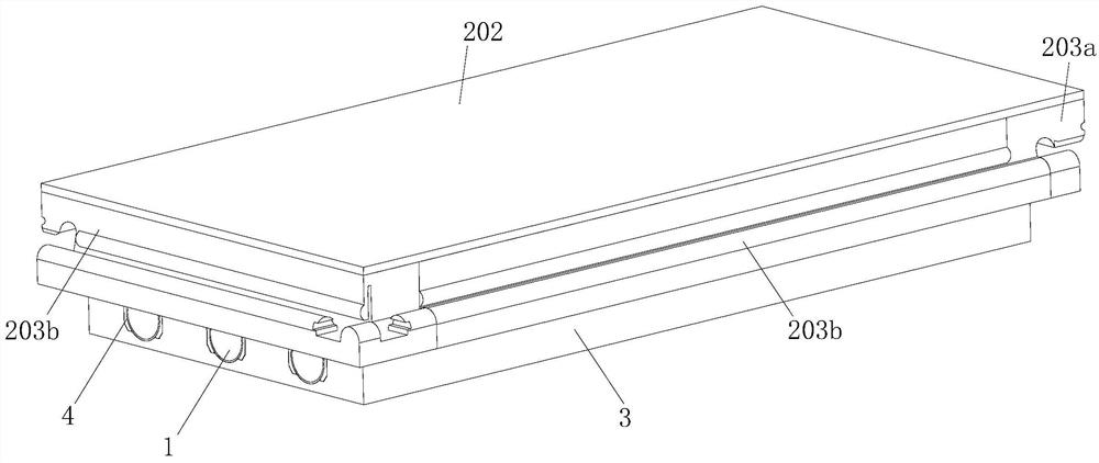
[0056] The key improvement of this embodiment is that each floor board 2 is composed of a metal corrugated board 201 , a panel 202 attached to and fixed on the top of the metal corrugated board, and a floor buckle 203 fixedly connected to the side of the metal corrugated board. The metal corrugated board 201 is laid on the floor heating pipe 1 and is thermally connected with the floor heating pipe 1 , and the floor boards 2 are connected by floor buckles 203 that are fastened to each other.
[0057] It can be seen that each floor plate 2 of this floor heating structure is directly paved above the floor heating pipe 1, and each floor plate 2 is connected to each other by means of the floor buckle 203 that comes with the floor plate 2 to...
Embodiment 2
[0081] Image 6It shows the second preferred embodiment of the floor heating structure of the present application, the floor heating structure is basically the same as the structure of the first embodiment, the difference is that the length of the heat pipe clamp 4 in this embodiment is basically equal to the length of the floor heating pipe 1 .
Embodiment 3
[0083] Figure 7 It shows the third preferred embodiment of the floor heating system of the present application. The structure of the floor heating system is basically the same as that of the first embodiment. The upper surface is covered with a layer of heat-conducting film 7, and part of the heat-conducting film 7 is sandwiched between the outer pipe wall of the floor heating pipe 1 and the groove wall of the pipe groove 301, and the metal corrugated board 201 (specifically, the lower plate body 201b) is attached to Arranged on the upper surface of the heat conduction film 7 . In this way, the heat conduction film 7 has a larger contact area with the floor heating pipe 1 and the metal honeycomb panel 201 , so that the heat of the floor heating pipe 1 can be quickly transferred to the metal honeycomb panel 201 .
[0084] The above-mentioned heat conduction film 7 is preferably aluminum foil.
PUM
 Abstract
Description
Claims
Application Information
 - Generate Ideas
- Intellectual Property
- Life Sciences
- Materials
- Tech Scout
- Unparalleled Data Quality
- Higher Quality Content
- 60% Fewer Hallucinations
Browse by: Latest US Patents, China's latest patents, Technical Efficacy Thesaurus, Application Domain, Technology Topic, Popular Technical Reports.
© 2025 PatSnap. All rights reserved.Legal|Privacy policy|Modern Slavery Act Transparency Statement|Sitemap|About US| Contact US: help@patsnap.com