
Oxide-reinforced low-activation steel, electroslag remelting slag system and smelting method

A low-activation steel and smelting method technology, applied in the field of electrometallurgy, can solve the problems of increased activity and low recovery rate of rare earth, and achieve the effects of increasing the reaction rate, uniform composition, and preventing the failure of arcing and slagging.

Active Publication Date: 2020-11-03
XI'AN UNIVERSITY OF ARCHITECTURE AND TECHNOLOGY
View PDF10 Cites 0 Cited by
  • Summary
  • Abstract
  • Description
  • Claims
  • Application Information

AI Technical Summary

Problems solved by technology

[0004] At present, the commonly used slag system for electroslag remelting is CaF 2 Main raw material, add A1 2 o 3 , CaO and other oxides; the basic slag system has CaF 2 -A1 2 o 3 Slag system (70%CaF 2 -30% A1 2 o 3 ) and CaF 2 -CaO-A1 2 o 3 Slag system (60%CaF 2 -20% A1 2 o 3 -20% CaO and 40% CaF 2 -30% A1 2 o 3 -30%CaO) two series, the above slag series all contain a certain mass fraction of A1 2 o 3 , A1 during smelting 2 o 3 Will enter the molten steel and pollute the low-activation steel, resulting in an increase in its activity
At the same time Y 2 o 3 For rare earth oxides, the problem of extremely low recovery rate of rare earth (less than 5%) in the electroslag remelting process has not been solved

Method used


Image

  • Oxide-reinforced low-activation steel, electroslag remelting slag system and smelting method
  • Oxide-reinforced low-activation steel, electroslag remelting slag system and smelting method

Examples


Embodiment 1

[0041] In the electroslag remelting slag system of this embodiment, the composition of the A slag includes: CaF 2 : 40 parts, Y 2 o 3 : 33 parts, CaO: 30 parts; The composition of described B slag comprises CaF 2 : 65 parts, CaO: 30 parts, MgO: 4 parts, SiO 2 :7 copies;

[0042] The smelting method of the oxide-reinforced low-activation steel in this embodiment comprises the following steps:

[0043] Step 1, pre-baking the slag A and the slag B before use, the temperature of the baking pre-treatment is 600°C, and the time is 6 hours;

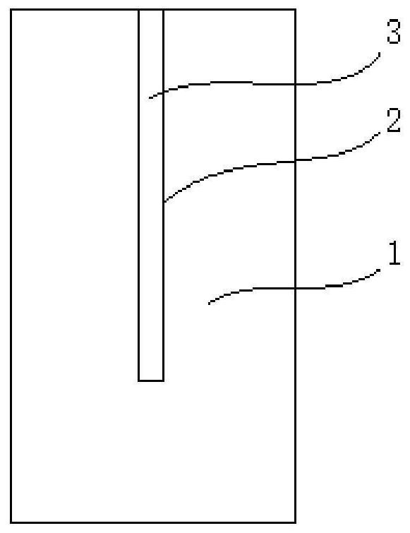
[0044] Step 2: Process a blind hole inward from the upper end of the consumable electrode, fill the blind hole with metal yttrium powder with a particle size ≤ 35 μm, and open the blind hole from top to bottom along the axis of the consumable electrode. The distance from the lower end of the electrode to the bottom of the blind hole is 1 / 15 of the total length of the consumable electrode; weld the upper end of the consumable electrode to th...

Embodiment 2

[0051] In the electroslag remelting slag system of this embodiment, the composition of the A slag includes: CaF 2 : 50 parts, Y 2 o 3 : 30 parts, CaO: 20 parts; The composition of described B slag comprises CaF 2 : 60 parts, CaO: 35 parts, MgO: 2 parts, SiO 2 :5 copies;

[0052] The smelting method of the oxide-reinforced low-activation steel in this embodiment comprises the following steps:

[0053] Step 1, pre-baking the slag A and the slag B before use, the temperature of the baking pre-treatment is 650°C, and the time is 8 hours;

[0054] Step 2: Process a blind hole inward from the upper end of the consumable electrode, fill the blind hole with metal yttrium powder with a particle size ≤ 35 μm, and open the blind hole from top to bottom along the axis of the consumable electrode. The distance from the lower end of the electrode to the bottom of the blind hole is 1 / 12 of the total length of the consumable electrode; weld the upper end of the consumable electrode to th...

Embodiment 3

[0061] In the electroslag remelting slag system of this embodiment, the composition of the A slag includes: CaF 2 :55 parts, Y 2 o 3 : 35 parts, CaO: 25 parts; The composition of described B slag comprises CaF 2 : 55 parts, CaO: 40 parts, MgO: 5 parts, SiO 2 :3 copies;

[0062] The smelting method of the oxide-reinforced low-activation steel in this embodiment comprises the following steps:

[0063] Step 1, pre-baking the slag A and the slag B before use, the temperature of the baking pre-treatment is 700°C, and the time is 10 hours;

[0064]Step 2: Process a blind hole inward from the upper end of the consumable electrode, fill the blind hole with metal yttrium powder with a particle size ≤ 35 μm, and open the blind hole from top to bottom along the axis of the consumable electrode. The distance from the lower end of the electrode to the bottom of the blind hole is 1 / 10 of the total length of the consumable electrode; weld the upper end of the consumable electrode to the...


PUM

PropertyMeasurementUnit
Yield strengthaaaaaaaaaa

Abstract

The invention discloses oxide-reinforced low-activation steel, an electroslag remelting slag system and a smelting method. The electroslag remelting slag system comprises slag A and slag B, the slag Acomprises the following components including, by mass, 40-55 parts of CaF2, 30-35 parts of Y2O3 and 20-30 parts of CaO, the slag B comprises the following components including, by mass, 55-65 parts of CaF2, 30-40 parts of CaO, 2-5 parts of MgO and 3-7 parts of SiO2; in the smelting process, a blind hole is machined inwards from the end face of the upper end of a consumable electrode, the blind hole is filled with yttrium, the upper end of the consumable electrode is welded to a fake electrode, the consumable electrode is fixed to a smelting position, the slag A is added into a water-cooling crystallizer, and arcing slagging is conducted; and smelting is started after arcing, the slag B is added after smelting to a designated position of the consumable electrode, smelting continues to be carried out until smelting is finished, and the designated position is a horizontal position corresponding to the bottom of the blind hole in the consumable electrode. The electroslag remelting slag system does not contain Al2O3, the smelting method can fully utilize the electroslag remelting slag system, the yield of Y is increased, and the new oxide-reinforced low-activation steel is obtained.

Description

technical field [0001] The invention relates to the field of electrometallurgy, in particular to an oxide-strengthened low-activation steel, an electroslag heavy melting slag system and a smelting method. Background technique [0002] Due to its excellent performance, low-activation steel is generally considered to be the preferred structural material for future fusion demonstration reactors and fusion power reactors. It adopts a low-activation design, that is, the radioactivity of the material after service needs to drop to the limit level (10mSv / h) that can be recycled within 100 years. Therefore, high-activity elements Al, Ni, Cu, Nb, Existence of Mo and Sn. In order to further improve the mechanical properties of low-activation steel, scholars at home and abroad have passed a large number of experimental studies and applied powder metallurgy technology to develop Y 2 o 3 Oxide strengthened low activation steel. At present, the uniform dispersion of oxide dispersed ph...

Claims


Application Information

Patent Timeline
IPC IPC(8): C22B9/18C22C33/04C22C38/02C22C38/04C22C38/22C22C38/24C22C38/28
CPCC22B9/18C22C33/04C22C38/02C22C38/04C22C38/22C22C38/24C22C38/28C22C38/005Y02P10/25
Inventor 邱国兴刘诗薇
Owner XI'AN UNIVERSITY OF ARCHITECTURE AND TECHNOLOGY
Learn More