
Torsion beam in passenger vehicle rear axle assembly

A technology of passenger cars and torsion beams, applied in the field of torsion beams, can solve the problems of increasing the manufacturing difficulty and production cost of torsion beams, unfavorable weight reduction of the vehicle body, complex structure and technology, etc., to achieve production cost reduction, reduce torsional stress, and improve molding quality effect

Pending Publication Date: 2020-11-03
湘潭地通汽车制品有限公司
View PDF5 Cites 2 Cited by
  • Summary
  • Abstract
  • Description
  • Claims
  • Application Information

AI Technical Summary

Problems solved by technology

[0003] There are two types of torsion beams, one is the "U"-shaped open beam, which uses the stamping process to press the high-strength steel plate into a "U" shape, and installs a circular cross-section torsion bar in the "U"-shaped open beam. This kind of structure is complex in technology, which is not conducive to the lightweight of the body; the other is the variable cross-section torsion beam, which stamps the hollow circular tube to form a "V" shaped cross-section torsion beam. Compared with the "U"-shaped open beam, this structure is lighter. , which can meet the requirements of vehicle fatigue durability and meet the requirements of light weight of the vehicle body
[0004] The forming processes of variable cross-section torsion beams include: internal high pressure forming, hot stamping forming and cold stamping forming. The production efficiency of internal high pressure forming and hot stamping forming processes is low, and the process equipment is complicated, which increases the manufacturing difficulty and production cost of the torsion beam.

Method used


Image

  • Torsion beam in passenger vehicle rear axle assembly
  • Torsion beam in passenger vehicle rear axle assembly
  • Torsion beam in passenger vehicle rear axle assembly

Examples


Embodiment Construction

[0020] In describing the present invention, it should be understood that the terms "center", "longitudinal", "transverse", "upper", "lower", "front", "rear", "left", "right", " The orientations or positional relationships indicated by "vertical", "horizontal", "top", "bottom", "inner" and "outer" are based on the orientations or positional relationships shown in the drawings, and are only for the convenience of describing the present invention and Simplified descriptions, rather than indicating or implying that the device or element referred to must have a particular orientation, be constructed and operate in a particular orientation, and thus should not be construed as limiting the invention. In addition, the terms "first", "second", etc. are used for descriptive purposes only, and should not be understood as indicating or implying relative importance or implicitly specifying the quantity of the indicated technical features. Thus, a feature defined as "first", "second", etc. ...


PUM


Abstract

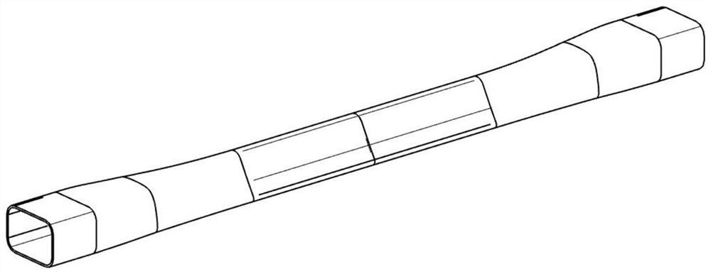
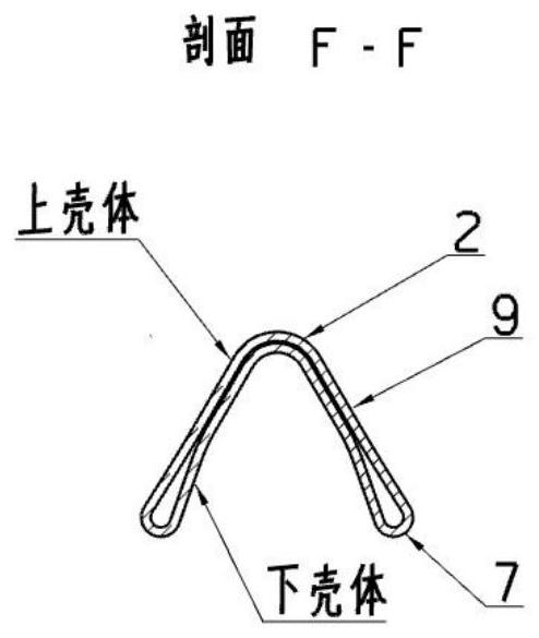
The invention discloses a torsion beam in a passenger car rear axle assembly, and the torsion beam comprises a beam body and a weld joint; the beam body is a bilaterally symmetrical variable cross-section hollow pipe beam and is formed by cold stamping forming and quenched-tempered heat treatment of a high-strength steel round pipe. The weld joint is located near a circular bead of an upper shellof a rectangular area of a torsion beam port and extends to the waist line position of the upper shell in the length direction, the port area is in a rectangular pipe shape subjected to rounding treatment, and the section structure of the middle area is in an inverted V shape formed by folding a closed curve. According to the invention, the high-strength steel seamless welding circular tube is used as a raw material of the torsion beam, so the production cost is greatly reduced compared with a V-shaped opening beam; the forming quality and the production efficiency of the product are improved;meanwhile, the modeling of the torsion beam is optimized through CAE simulation, so the longitudinal rigidity, the lateral rigidity and the roll rigidity of torsion can be effectively improved, the torsion stress of the torsion beam is effectively reduced, and the fatigue durability is improved.

Description

technical field [0001] The invention relates to the technical field of chassis suspension components of passenger cars, in particular to a torsion beam in a rear axle assembly of a passenger car. Background technique [0002] The torsion beam of a passenger car connects the left and right trailing arms to form a semi-independent rear suspension with a certain torsional rigidity. During the driving process of the car, the torsion beam bears the impact force of the road surface transmitted by the rear wheels and undergoes torsional deformation. When rolling, ensure the handling performance and driving stability of the car. At present, this kind of torsion beam rear suspension is mostly used in family cars and small passenger cars. [0003] There are two types of torsion beams, one is the "U"-shaped open beam, which uses the stamping process to press the high-strength steel plate into a "U" shape, and installs a circular cross-section torsion bar in the "U"-shaped open beam. ...

Claims


Application Information

Patent Timeline
Patent Type & Authority Applications(China)
IPC IPC(8): B60G21/05
CPCB60G21/051B60G2200/21B60G2206/8102B60G2206/8106B60G2206/8201
Inventor 何烨
Owner 湘潭地通汽车制品有限公司
Learn More