Heat dissipation structure suitable for spacecraft high-power device

A high-power device, heat dissipation structure technology, applied to the circuit layout on the support structure, electrical components, circuit layout on the insulating board, etc., can solve the problem of low normal heat transfer coefficient and can not play the role of high-power device insulation protection effect, adverse device thermal reliability design, etc.

Active Publication Date: 2020-10-30
BEIJING SATELLITE MFG FACTORY
View PDF21 Cites 3 Cited by
  • Summary
  • Abstract
  • Description
  • Claims
  • Application Information

AI Technical Summary

Problems solved by technology

[0004] Some traditional high-power devices are directly installed on the printed board, which is convenient for the insulation installation of the device. However, due to the low normal heat transfer coefficient of the printed board, it is easy to generate heat accumulation during the thermal shock process, causing the junction temperature of the device to Significantly increased, resulting in reduced service life of high-power devices and reduced product reliability
[0005] In addition, high-power devices are directly mounted on the structure, which theoretically reduces the heat conduction distance between the device and the heat dissipation surface, but due to the rigid installation, the contact thermal resistance between the device and the heat dissipation surface is increased. Additional measures are required to insulate the mounting of high power devices
[0006] The power device installation methods disclosed at present still have the following...

Method used


Image

  • Heat dissipation structure suitable for spacecraft high-power device
  • Heat dissipation structure suitable for spacecraft high-power device

Examples


Embodiment Construction

[0030] The present invention will be described in further detail below in conjunction with the accompanying drawings.

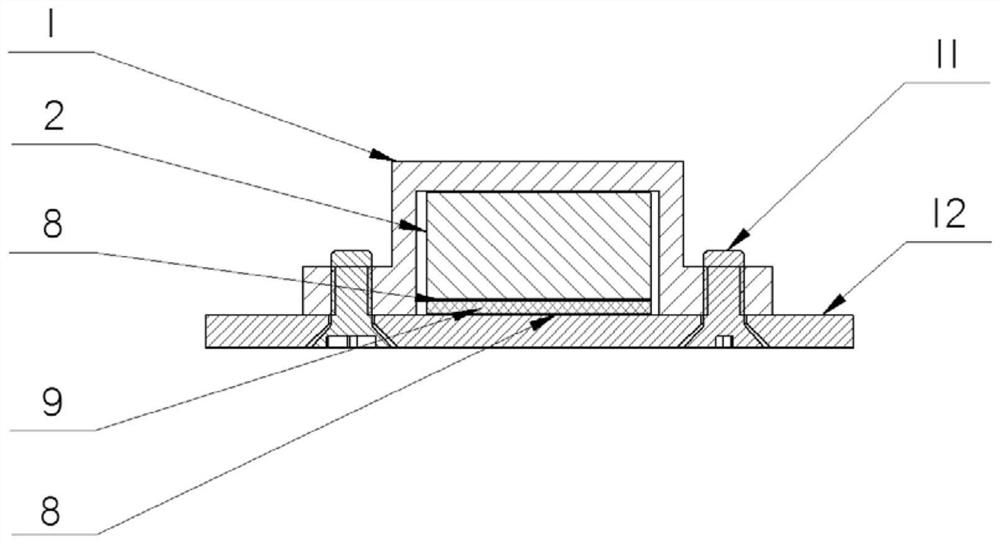
[0031] A heat dissipation structure suitable for spacecraft high-power devices, such as figure 1 , 2 As mentioned above, it includes the installation pressing block 1, the elastic sponge body 2, the insulating sleeve 7, the first thermally conductive filler 8, the insulating ceramic sheet 9, the second thermally conductive filler 10 and the mounting plate 12,

[0032] The mounting plate 12 is the main mounting structure of the single-ear high-power device, and the insulating ceramic sheet 9 is placed on the mounting plate 12, and the thermally conductive filler 10 is evenly applied between the insulating ceramic sheet 9 and the mounting plate 12,

[0033] The single-ear high-power device is placed on the insulating ceramic sheet 9, and the heat-conducting filler 8 is evenly applied between the insulating ceramic sheet 9 and the high-power device, and the ins...


PUM

PropertyMeasurementUnit
Tensile strengthaaaaaaaaaa
Breakdown strengthaaaaaaaaaa
Thicknessaaaaaaaaaa

Abstract

The invention relates to a heat dissipation structure suitable for a spacecraft high-power device. The structure comprises an installation pressing block, an elastic sponge body, heat conduction filler, an insulation ceramic piece, an insulation sleeve and an installation plate. The installation plate and the installation pressing block are main heat dissipation structures, a single-lug high-powerdevice is fixed to the installation plate, the insulation ceramic piece is arranged between the installation plate and the device, and the heat conduction filler is evenly smeared at the gap betweenthe installation plate and the device; a fastener and a metal shell of the single-lug high-power device are isolated by using a T-shaped insulating sleeve; and the elastic sponge body is loaded between the installation pressing block and the device to provide uniform pressing force for the mounting surface of the device. According to the structure, a large-area heat conduction path does not need to be drawn, active thermal control measures do not need to be provided, the temperature rise suppression amplitude of the single-lug high-power device can reach 23% or above, the insulation and voltage resistance of 10 kV or above can be achieved, and the structure can be widely applied to insulation and heat dissipation installation of the spacecraft high-power device.

Description

technical field [0001] The invention relates to a heat dissipation structure suitable for high-power devices of spacecraft, which can be widely applied to the heat dissipation installation and insulation installation of single-ear high-power devices in aerospace electronic products, so that the single-ear high-power devices can not only meet the requirements of insulation installation, but also can Withstand the harsh thermal shock test environment, so that the single-ear high-power devices do not suffer from temperature failures such as excessive junction temperature. Background technique [0002] High-power devices are electronic switching components commonly used in aerospace electronic products. In order to prevent short-circuit damage to the command bus caused by short-circuit of high-power devices, high-power devices need to be insulated and installed; at the same time, in order to meet the requirements of spacecraft thermal environmental conditions, The junction tempe...

Claims


Application Information

Patent Timeline
IPC IPC(8): H05K7/20H05K7/08
CPCH05K7/20472H05K7/08
Inventor 宋伟蔺鹏婷许志尧裴行政纪志坡陈永刚
Owner BEIJING SATELLITE MFG FACTORY
Why Eureka
Try Eureka