
Power battery self-heating method, device and readable storage medium

A power battery and self-heating technology, which is applied to secondary batteries, circuits, electrical components, etc., can solve the problems of battery capacity attenuation, battery power consumption, and inability to use, and achieve the effect of avoiding battery life decline

Active Publication Date: 2022-07-12
SUNWODA ELECTRIC VEHICLE BATTERY CO LTD
View PDF5 Cites 0 Cited by
  • Summary
  • Abstract
  • Description
  • Claims
  • Application Information

AI Technical Summary

Problems solved by technology

[0003] At present, for the thermal management system for heating the battery, an external heater or self-heating technology can be used to realize it, but common external heaters such as PTC (Positive Thermal Coefficient) thermistors or liquid pipes, etc., have low heating efficiency. Low; while in the prior art, the internal resistance is usually used to generate ohmic heat to achieve internal heating of the battery, such as using pulse discharge to self-heat the battery. This method needs to consume battery power and cannot be used when the power is insufficient; One way is to use repeated pulse charge and discharge to raise the battery temperature, but this method mainly determines the pulse frequency through electrochemical impedance spectroscopy, and uses the boundary voltage of lithium analysis and side reactions to determine the charge and discharge pulse amplitude. On the one hand, each frequency It is difficult to determine the lithium analysis and side reaction voltage under the condition of lithium ionization. On the other hand, the problem of battery capacity attenuation is not considered, which may lead to battery capacity attenuation and shorten battery life under repeated pulse charge and discharge conditions.

Method used


Image

  • Power battery self-heating method, device and readable storage medium
  • Power battery self-heating method, device and readable storage medium
  • Power battery self-heating method, device and readable storage medium

Examples


Embodiment Construction

[0050] The technical solutions in the embodiments of the present application will be clearly and completely described below with reference to the drawings in the embodiments of the present application. Obviously, the described embodiments are only a part of the embodiments of the present application, rather than all the embodiments. Based on the embodiments in the present application, all other embodiments obtained by those of ordinary skill in the art without creative work fall within the protection scope of the present application.

[0051] In addition, descriptions such as "first", "second", etc. in this application are only for descriptive purposes, and should not be construed as indicating or implying their relative importance or implicitly indicating the number of indicated technical features. Thus, a feature delimited with "first", "second" may expressly or implicitly include at least one of that feature. In addition, the technical solutions between the various embodime...


PUM


Abstract

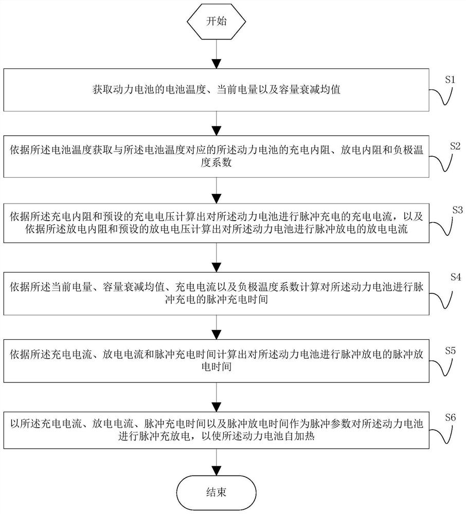
The present application discloses a self-heating method, device and readable storage medium for a power battery, wherein the method includes: acquiring the battery temperature, current power and average capacity attenuation of the power battery; acquiring corresponding charging internal resistance and discharging internal resistance according to the battery temperature and negative temperature coefficient; calculate the charging current according to the charging internal resistance and charging voltage, calculate the discharging current according to the discharging internal resistance and discharging voltage; The pulse discharge time is calculated by the current, discharge current and pulse charging time; the power battery is charged and discharged by pulse using the charging current, discharge current, pulse charging time and pulse discharge time as the pulse parameters, so that the power battery is self-heating, which will not cause Lithium is precipitated in the negative electrode, and the self-heating battery has no obvious capacity decay, which can avoid the decline of battery life due to cyclic charge and discharge.

Description

technical field [0001] The present application relates to the technical field of power battery thermal management, and in particular to a power battery self-heating method, device and readable storage medium. Background technique [0002] Lithium-ion power batteries use graphite as the negative electrode. When charging at low temperature, the negative electrode is prone to lithium precipitation or other side reactions, which will lead to a decrease in the cruising range of electric vehicles and even serious safety problems. Therefore, the thermal management system of the battery pack heats the battery before charging it at low temperatures. [0003] At present, the thermal management system for heating the battery can be realized by using an external heater or using self-heating technology, but common external heaters such as PTC (Positive Thermal Coefficient) thermistor or liquid pipeline, etc., have high heating efficiency. In the prior art, the internal resistance is usu...

Claims


Application Information

Patent Timeline
Patent Type & Authority Patents(China)
IPC IPC(8): H01M10/615H01M10/625H01M10/633H01M10/637
CPCH01M10/615H01M10/625H01M10/633H01M10/637Y02E60/10
Inventor 方杰刘华涛张耀
Owner SUNWODA ELECTRIC VEHICLE BATTERY CO LTD
Learn More