
Deep learning wavefront restoration method based on single-frame focal plane light intensity image

A deep learning and wavefront restoration technology, applied in neural learning methods, image enhancement, measurement optics, etc., can solve problems such as lack of speed, affecting the accuracy of wavefront restoration, and achieve simple structure, high light energy utilization, and improved computing. The effect of efficiency

Active Publication Date: 2020-10-30
INST OF OPTICS & ELECTRONICS - CHINESE ACAD OF SCI
View PDF13 Cites 0 Cited by
  • Summary
  • Abstract
  • Description
  • Claims
  • Application Information

AI Technical Summary

Problems solved by technology

[0003] However, the effectiveness of the walsh function phase plate to modulate the far field to the wavefront restoration results not only depends on whether the correct shape of the walsh function with non-180° rotation and flip symmetry is selected, but also on the relationship between different order walsh functions and the phase step depth of the photo. The selection will also affect the accuracy of wavefront restoration
Moreover, the improved algorithm still continues the iterative solution of the traditional phase inversion method. Although the number of iterations is relatively reduced, there is still a lack of speed.

Method used


Image

  • Deep learning wavefront restoration method based on single-frame focal plane light intensity image
  • Deep learning wavefront restoration method based on single-frame focal plane light intensity image
  • Deep learning wavefront restoration method based on single-frame focal plane light intensity image

Examples


Embodiment Construction

[0040] In order to make the object, technical solution and advantages of the present invention clearer, the present invention will be further described in detail below in conjunction with specific embodiments and with reference to the accompanying drawings.

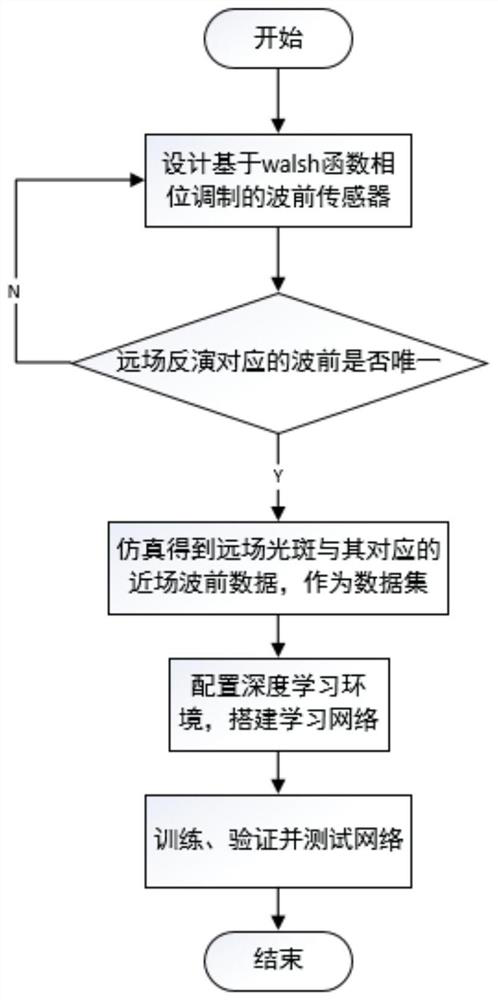
[0041] figure 1 It is a flow chart of a deep learning wavefront restoration method based on a single-frame focal plane light intensity image. The specific implementation process is:

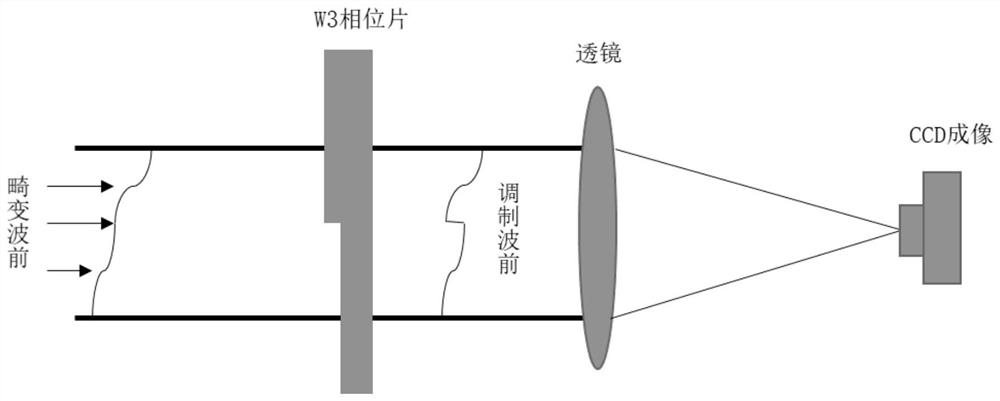
[0042] Step 1: Design a wavefront sensor based on walsh function phase modulation. After comparing the simulation results, choose the W3 function as the phase plate, as shown in figure 2 Shown is the schematic diagram of the wavefront sensor based on W3 phase plate modulation;

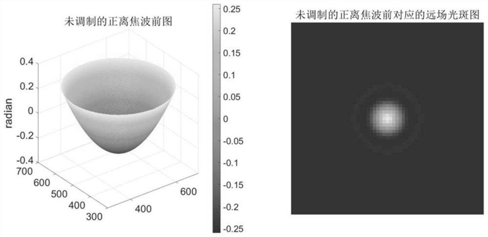
[0043] Step 2: Through the positive and negative defocus wavefronts characterized by Zernike polynomials, verify whether the sensor designed in step 1 can ensure that the far-field spot distribution corresponds to only one wavefront information, that is, the soluti...


PUM


Abstract

The invention discloses a deep learning wavefront restoration method based on a single-frame focal plane light intensity image, and aims to solve the problem that multiple solutions exist when a single far-field light spot inverts a near-field wavefront due to the fact that two groups of wavefronts which mutually rotate by 180 degrees and have a complex conjugate relationship in an adaptive optical system have the same far-field light spot distribution. The wavefront restoration method based on walsh function phase modulation can ensure that far-field light spot distribution corresponds to a unique near-field wavefront, but the calculation speed is still limited by the number of iterations and the single-step iterative calculation time. The deep learning algorithm can self-extract the deepfeature information of the image, so that the mapping relation from the far-field light intensity image to the near-field wavefront can be learned on the basis of phase modulation of the walsh function, the calculation from the far-field image to the near-field wavefront end-to-end is realized, and the iterative calculation process of the traditional wavefront restoration method can be avoided. Based on this, the iterative calculation process of a traditional wavefront restoration method is avoided by using a deep learning algorithm, the calculation efficiency is improved, and rapid wavefrontrestoration of a single-frame focal plane light intensity image is realized.

Description

technical field [0001] The present invention relates to a wavefront restoration method, in particular to a deep learning wavefront restoration method based on a single-frame focal plane light intensity image. Background technique [0002] In the adaptive optics system, Zernike polynomials are often used to characterize the wavefront in the circular domain, and different sets of Zernike coefficients can be selected to generate different random wavefront aberrations. However, when the two sets of wavefronts have a complex conjugate relationship of 180° rotation to each other, they will produce the same far-field spot distribution. In this case, the traditional wavefront restoration algorithm is used to invert the near-field wavefront phase from a single far-field spot. , the resulting corresponding wavefront is not unique, which will lead to wrong solutions or even failure to converge in the restoration calculation. The wavefront restoration algorithm based on walsh function ...

Claims


Application Information

Patent Timeline
IPC IPC(8): G01J9/00G06N3/04G06N3/08G06T5/00
CPCG01J9/00G06N3/08G01J2009/002G06T2207/20081G06T2207/20084G06N3/045G06T5/77
Inventor 孔令曦程涛邱学晶杨超王帅杨平
Owner INST OF OPTICS & ELECTRONICS - CHINESE ACAD OF SCI
Learn More