
A connection method of steel material and carbon fiber braid

A technology of carbon fiber weaving and connecting method, which is applied in welding equipment, laser welding equipment, metal processing equipment, etc., can solve the problems of damage to composite material structure, low production efficiency, and waste of materials, so as to avoid the damage of epoxy resin and minimize the Effects of weight reduction and process difficulty reduction

Active Publication Date: 2021-11-02
HARBIN INST OF TECH
View PDF8 Cites 0 Cited by
  • Summary
  • Abstract
  • Description
  • Claims
  • Application Information

AI Technical Summary

Problems solved by technology

Nowadays, the connection process between carbon fiber composite materials and steel materials includes glue joints and bolted joints, but the former has the problems of low strength and poor reliability, while the latter needs to be pre-punched, which has low production efficiency and wastes materials. The structure of the material, resulting in a decrease in strength

Method used


Image

  • A connection method of steel material and carbon fiber braid
  • A connection method of steel material and carbon fiber braid
  • A connection method of steel material and carbon fiber braid

Examples


specific Embodiment approach 1

[0026] Embodiment 1: In this embodiment, a method for connecting a steel material and a carbon fiber braid is specifically carried out in the following steps:

[0027] 1. Use carbon fiber weaving device to weave carbon fiber to obtain carbon fiber cloth;

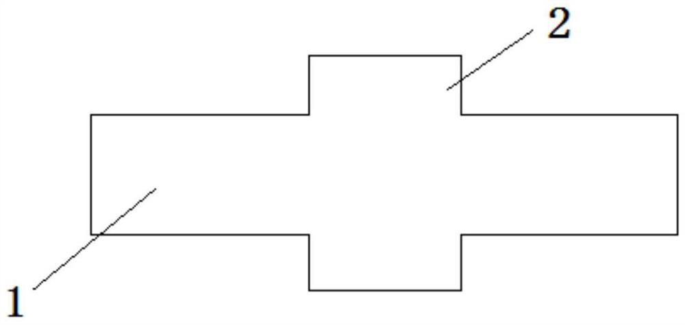
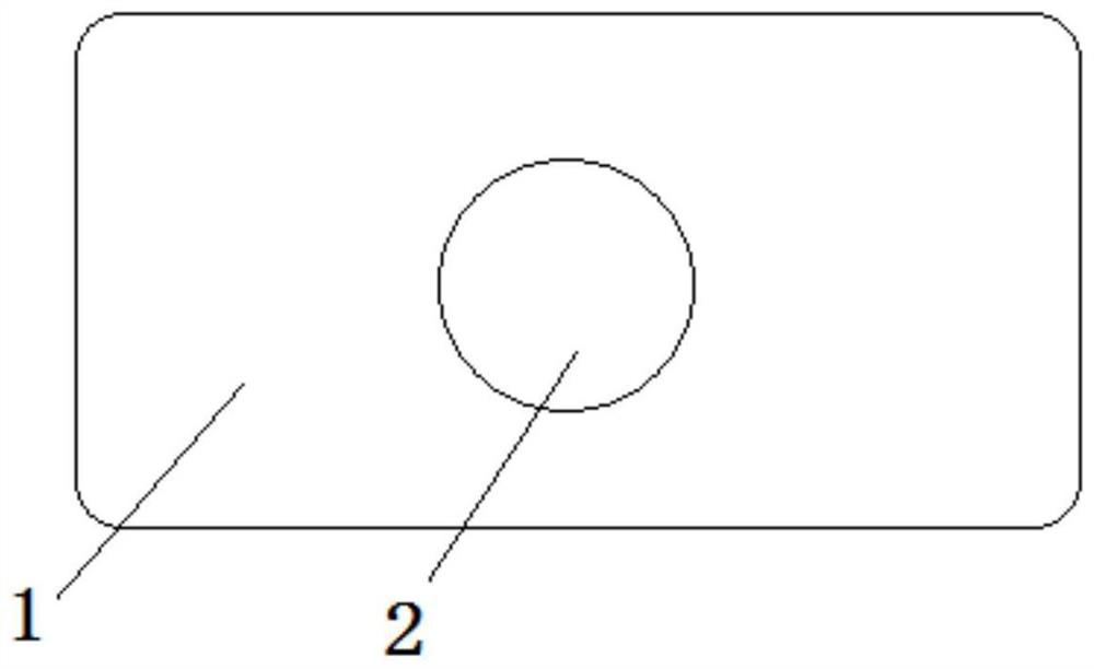
[0028] 2. Process the steel into a connecting body; the connecting body is composed of a main body and a connecting protrusion, and the connecting protrusions are respectively located on the upper surface and the lower surface of the main body;

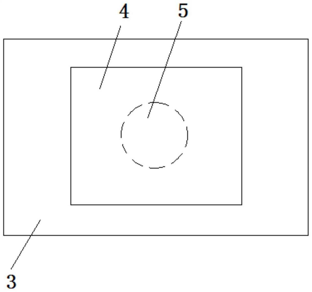
[0029] 3. Cut out holes in the carbon fiber cloth obtained in step 1;

[0030] 4. Pretreat the connected body obtained in step 2, and then wrap the connected body with glass fiber cloth to expose the raised end face of the connection, and then pave it with the carbon fiber cloth cut in step 3 on the wet molding mold. Obtain the carbon fiber cloth paving body embedded with the connector, then close the mold, inject preheated epoxy resin, perform molding by wet molding process, open ...

specific Embodiment approach 2

[0032] Specific embodiment 2: The difference between this embodiment and specific embodiment 1 is that the main body of the connecting body in step 2 is a rectangular structure with rounded corners, and the connecting protrusion is a cylinder with a height of 1.5-3 mm. The diameter of the bottom surface is 10-15 mm. Others are the same as in the first embodiment.

[0033] Specific embodiment 2: The difference between this embodiment and specific embodiment 1 or 2 is that the density of the carbon fiber cloth after cutting in step 3 is 0.2-0.8 g / cm 3 . Others are the same as in the first or second embodiment.

specific Embodiment approach 4

[0034] Embodiment 4: The difference between this embodiment and one of Embodiments 1 to 3 is that the hole cut out in step 3 matches the connecting body. Others are the same as those in the first to third specific embodiments.


PUM

PropertyMeasurementUnit
heightaaaaaaaaaa
diameteraaaaaaaaaa
densityaaaaaaaaaa

Abstract

A method for connecting a steel material and a carbon fiber braid, and the invention relates to the field of connection between a steel material and a carbon fiber braid. The invention aims to solve the technical problem that carbon fiber composite material and metal are difficult to weld. Method: 1. Weaving to obtain carbon fiber cloth; 2. Processing the steel into a connecting body; 3. Cutting the carbon fiber cloth; 4. Wrapping the connecting body with glass fiber cloth, and then laying the carbon fiber cloth on a wet molding mold. Carry out wet compression molding; 5. Welding. The invention adopts the molding process of the metal joint and the composite material, transforms the connection between the carbon fiber composite material and the metal into the connection between the metal and the metal, reduces the difficulty of the process, and solves the problem that the connection between the carbon fiber and the metal is difficult. The invention is used for the connection of steel material and carbon fiber braided parts.

Description

technical field [0001] The invention relates to the field of connection of steel materials and carbon fiber braided pieces. Background technique [0002] In recent years, carbon fiber composite materials have gradually become the materials favored by automobile manufacturers due to their small weight, high strength, high rigidity, excellent creep resistance and corrosion resistance. In addition, the chemical properties of carbon fiber composite materials are stable, and their service life is 2 to 3 times that of steel; the deformation is small in the collision, the damage to the driver is small, and the safety is high; it has a more beautiful appearance. At the same time, the rapid development of new energy vehicles has provided great opportunities for the carbon fiber industry. Therefore, the subject of carbon fiber composite materials to manufacture auto parts and even car bodies has very attractive prospects. Nowadays, the connection process of carbon fiber composite mat...

Claims


Application Information

Patent Timeline
Patent Type & Authority Patents(China)
IPC IPC(8): B29C70/68B23K26/21B23K26/324
CPCB23K26/324B29C70/68B29C70/681B29C70/683B23K26/21
Inventor 王刚张闰勃
Owner HARBIN INST OF TECH
Learn More