
Vertical stone grinding equipment

A stone and equipment technology, applied in the field of vertical stone grinding equipment, can solve the problems of different weights at both ends of the railing, one-sided force on the clamping workbench, and influence on service life, etc., to achieve small footprint, stable force, The effect of high production efficiency

Pending Publication Date: 2020-10-30
泉州市嘉信机械制造有限公司
View PDF2 Cites 3 Cited by
  • Summary
  • Abstract
  • Description
  • Claims
  • Application Information

AI Technical Summary

Problems solved by technology

The grinding main machine adopted by the stone grinding machine, its grinding component can swing with the support plate, so as to ensure that when grinding the curved surface, the abrasive tool on the grinding component can also be in good contact with the stone, and the grinding effect is relatively good; However, the clamping workbench used by this stone grinding machine is a horizontal workbench, which occupies a relatively large area, and because the weights at both ends of the railing are usually different, it is easy to cause clamping when the processing station is automatically changed. Unilateral force on the workbench affects the service life

Method used


Image

  • Vertical stone grinding equipment
  • Vertical stone grinding equipment
  • Vertical stone grinding equipment

Examples


Embodiment 1

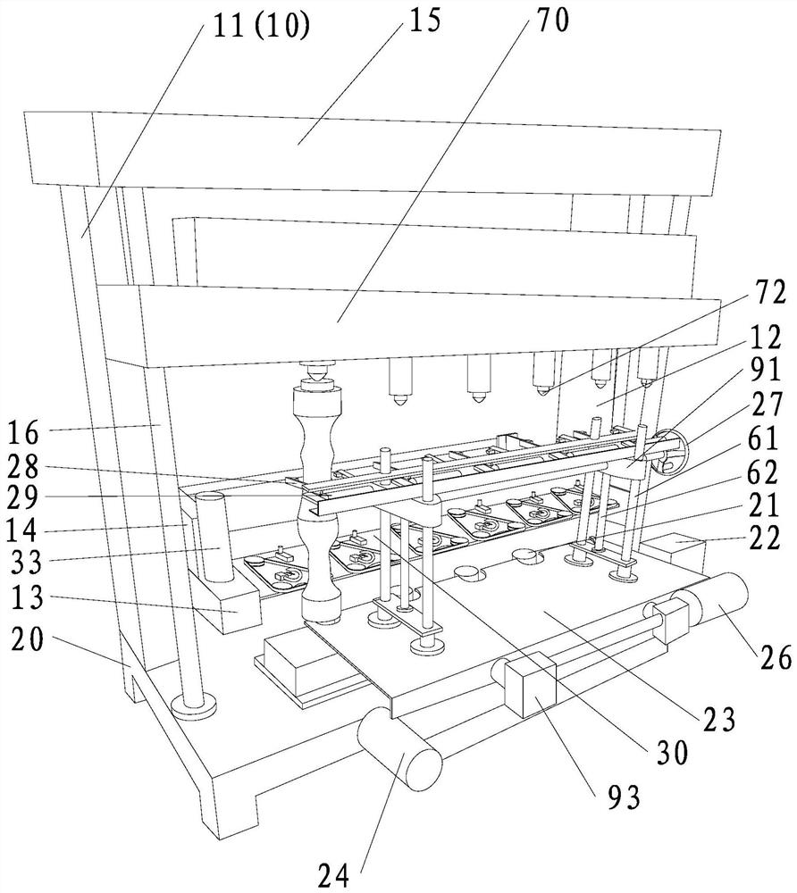
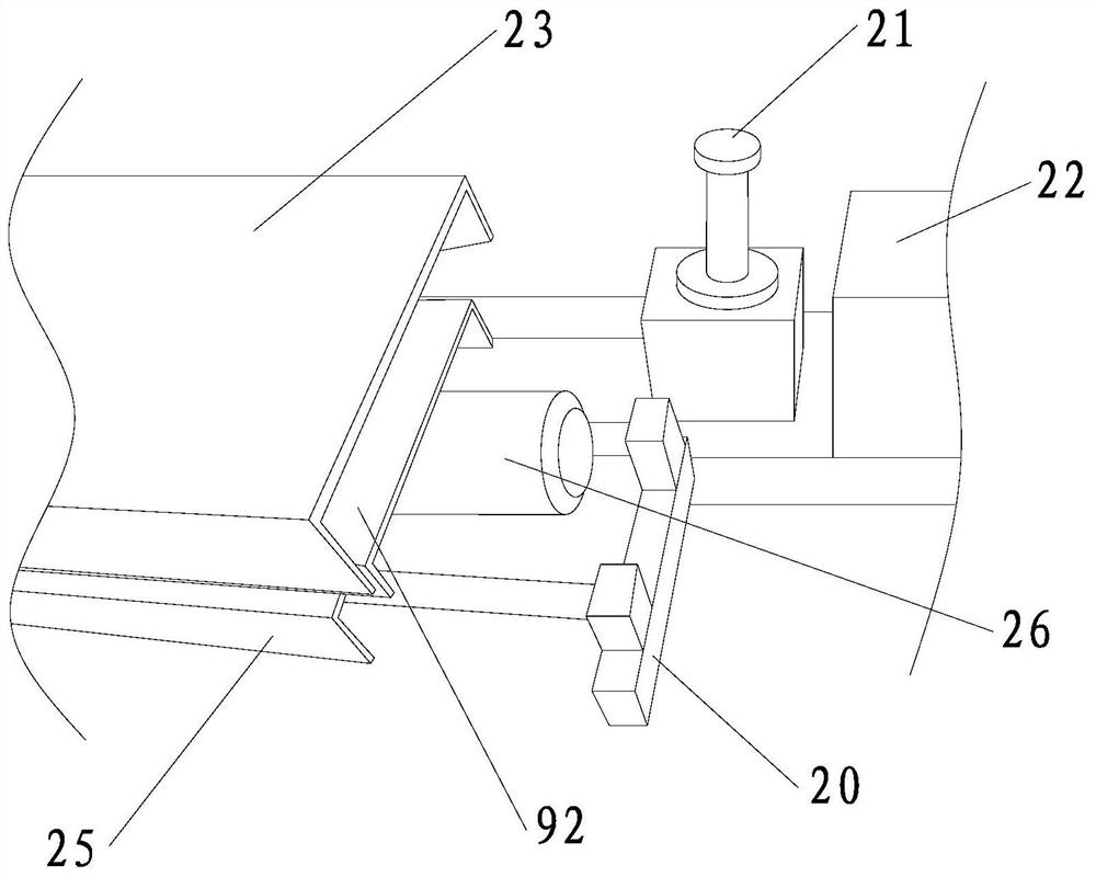
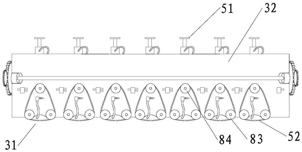
[0053] like Figure 1-Figure 4 As shown, the vertical stone grinding equipment provided in this embodiment is mainly used for grinding strip-shaped stone such as railings and stone pillars. The rack 10 has vertically arranged first uprights 11 and second uprights 12. The number of the first uprights 11 and the second uprights 12 can be determined according to actual needs. In this embodiment, the first uprights 11 and the second uprights 12 are each There is an example to illustrate, a top beam 15 is connected between the top of the first column 11 and the top of the second column 12 to improve the stability of the rack 10 . The upright column 11 and the second upright column 12 are respectively connected with a lift seat 13 in a vertical sliding manner. It should be noted that when there are multiple first upright columns 11 or second upright columns 12, the corresponding lift seats 13 are vertically slidably connected to each of them at the same time. There are only two lif...

Embodiment 2

[0067] like Image 6 As shown, the difference between this embodiment and the first embodiment is that the structure of the clamping jaws 28 is different. Specifically, in this embodiment, the clamping jaws 28 include first sliders that are respectively horizontally slidably connected to the clamping frame 91 . 67 and the second sliding block 68, the first clamping rod 65 fixedly connected with the first sliding block 67, the second clamping rod 66 fixedly connected with the second sliding block 68, and the middle part of the rod body is rotatably connected to the clamping frame 91 and the first link 94 and the second link 95 rotatably connected to both ends of the intermediate link 69, wherein the end of the first link 94 away from the intermediate link 69 rotates with the first clamping rod 65 For connection, one end of the second link 95 away from the intermediate link 69 is rotatably connected with the second link 95 . The number of clamping jaw driving devices 29 is the ...


PUM


Abstract

The invention provides vertical stone grinding equipment. The equipment comprises a machine frame, a base, supporting plates, a supporting motor, a lifting frame, a lifting driving device, a steppingplate, a stepping driving device, a clamping frame, a clamping driving device, clamping jaws, a clamping jaw driving device and other parts, wherein the arrangement directions of the supporting plates, the sliding direction of the stepping plate and the arrangement directions of the clamping jaws are the same, and the distance between two adjacent supporting plates is the same as the distance between the adjacent clamping jaws. Through the arrangement of the lifting frame, the stepping plate and the clamping jaws, movement of vertical stone between two adjacent supporting plates can be achieved, when the vertical stone moves, similar hand-held operation of the clamping jaws can be achieved, the vertical stone is effectively prevented from dumping during the movement, and the clamping of the vertical stone during automatic replacement of stations can be achieved, so that the vertical processing is achieved, the occupied area is relatively small, due to the fact that the weight of the vertical stone is mainly concentrated on the supporting plates, the force is stable, and the service life is relatively long.

Description

technical field [0001] The invention relates to a stone processing equipment, in particular to a vertical stone grinding equipment. Background technique [0002] After the strip stone products such as stone railings are cut, the surface usually needs to be polished to make them have a bright effect. At present, the polishing of stone products is mainly done manually, the production efficiency is relatively low, and the polishing The quality is less stable (influenced by worker proficiency and fatigue). [0003] The Chinese invention patent application with application publication number CN108857751A discloses a stone grinding machine, including a frame, a clamping table, a traverse frame, a lifting frame, a traverse driving device, a lifting driving device and a grinding host, the grinding host Including a grinding bracket, a rotating rod, a rotary drive device, a fixed gear or a fixed sprocket, a support plate, a fan-shaped plate, an arc-shaped rack or chain, and a grindin...

Claims


Application Information

Patent Timeline
Patent Type & Authority Applications(China)
IPC IPC(8): B24B7/22B24B41/02B24B41/00B24B41/06B24B27/00B24B47/06
CPCB24B7/22B24B41/02B24B41/005B24B41/06B24B27/0076B24B47/06
Inventor 李福山
Owner 泉州市嘉信机械制造有限公司
Learn More