
Disinfection system and disinfection device

A disinfection water and switch technology, which is applied in disinfection, water supply devices, sanitary equipment for toilets, etc., can solve the problems of not realizing regular opening of disinfection, unable to close in time, personal injury, etc.

Inactive Publication Date: 2020-10-30
上海荇衍生物科技工程有限公司
View PDF8 Cites 2 Cited by
  • Summary
  • Abstract
  • Description
  • Claims
  • Application Information

AI Technical Summary

Problems solved by technology

The technology of this existing patent cannot be moved smartly, nor can it be opened at regular intervals, and manual operation is required. When someone intrudes inadvertently during the opening period, it cannot be closed in time, which will bring certain injuries and troubles to personnel.
[0004] The above-mentioned invention has not yet realized the functions of being able to move, disinfecting at regular intervals, and effectively avoiding spraying to personnel during disinfection

Method used


Image

  • Disinfection system and disinfection device
  • Disinfection system and disinfection device
  • Disinfection system and disinfection device

Examples


Embodiment 1

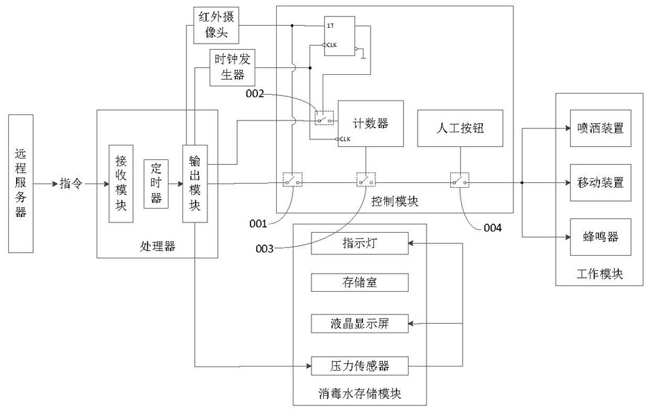
[0032] This embodiment discloses a disinfection system, as attached figure 1 As shown, the remote server sends an instruction to the corresponding disinfection device, and the disinfection device receives the instruction and controls the operation of the disinfection device according to the content of the instruction. Specifically, the disinfection system of this embodiment includes a remote server, a processor, a control module, a working module, a disinfectant water storage module, a personnel detection module and a casing. Wherein, the processor, the control module, the working module, the disinfectant water storage module and the personnel detection module are all installed in the casing. The processor includes receiving module, timer and output module. Wherein, the receiving module of the processor is used to receive the instruction transmitted by the remote server, and the instruction content transmitted by the remote server includes the timing setting content of the ti...

Embodiment 2

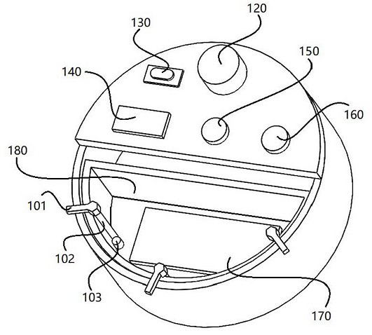
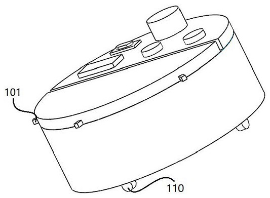
[0046] This embodiment discloses a disinfection device, which uses the disinfection system described in the first embodiment to work. The schematic diagram of the disinfection device of the present embodiment is as attached figure 2 As shown, a circular disinfection device is adopted, and a roller 110 is arranged at the bottom of the disinfection device for automatic movement of the position; The bottom is provided with a pressure sensor 170 for bearing the gravity of the disinfectant inside the storage chamber 180 . The indicator light 150 and the liquid crystal display 140 electrically connected to the pressure sensor 170 are both arranged on the outer upper surface of the disinfection device for visually observing the remaining liquid inside the storage chamber 180 and visually prompting that the amount of disinfectant water is too low and needs to be added. This embodiment is also provided with an infrared camera 120, which is also arranged on the outer upper surface of ...


PUM


Abstract

The invention discloses a disinfection system which comprises a remote server, a processor, a control module, a working module and a disinfectant fluid storage module, the processor comprises a receiving module, a timer and an output module, the receiving module receives an instruction transmitted by the remote server, the timer is used for controlling the output module to output a control signalregularly, the output module of the processor is connected with the input end of the control module, the input end of the working module is connected with the output end of the control module, and theworking module controls the working state according to the output result of the output end of the control module. The disinfectant fluid storage module comprises a storage chamber used for storing disinfectant fluid. The invention further discloses a disinfection device. According to the invention, the purposes of automatically and regularly spraying disinfectant and timely suspending the disinfection process in the presence of people can be achieved.

Description

technical field [0001] The invention belongs to the technical field of medical disinfection equipment control, in particular to a disinfection system and a disinfection device. Background technique [0002] As a public place where patients gather, the hospital is a place seriously polluted by pathogenic microorganisms. Therefore, daily disinfection and purification of the hospital is one of the daily tasks that the hospital must do. In the prior art, methods for disinfecting the hospital environment include ultraviolet disinfection, spraying disinfectant and the like. The ultraviolet disinfection method has the characteristics that it can be turned on at will, and it is quiet and silent. It is easy for patients or family members to turn on the ultraviolet lamp without care or lack of common sense; when there are people sleeping around or just doing other things in silence, it is very easy to turn on the ultraviolet lamp Without being detected, it is very easy to burn eyes...

Claims


Application Information

Patent Timeline
Patent Type & Authority Applications(China)
IPC IPC(8): A61L2/24A61L2/18A61L2/26
CPCA61L2/18A61L2/24A61L2/26A61L2202/14A61L2202/16
Inventor 周跃伟戴源
Owner 上海荇衍生物科技工程有限公司
Learn More