
Steel ladle argon blowing upper water gap brick cup and preparation method thereof

A technology for nozzle block and ladle, applied in the direction of manufacturing tools, casting equipment, metal processing equipment, etc., can solve problems such as affecting the service life, air leakage, furnace mismatch, etc., and achieve the effect of prolonging the service life and improving the service life.

Active Publication Date: 2020-10-27
LAIWU STEEL YINSHAN SECTION CO LTD
View PDF10 Cites 2 Cited by
  • Summary
  • Abstract
  • Description
  • Claims
  • Application Information

AI Technical Summary

Problems solved by technology

At present, domestic LF refining ladles of more than 100 tons generally use two bottom blowing air bricks. The processing time of high-quality steel is generally more than 40 minutes, of which soft blowing is 8-12 minutes. At present, there are the following problems or deficiencies in production practice: (1 ) Insufficient soft blowing time, which affects the removal effect of inclusions; (2) Too long LF refining time causes mismatch of furnace and machine, which becomes a restrictive link for increasing production and efficiency
However, in the nozzle seat brick in this patent, when the breathable ring is positioned in the mold for preparing the ventilating upper nozzle seat brick body of the ladle, and during the pouring process of the castable, the air chamber is easy to enter the castable foreign matter, which will affect the air permeability and the air intake pipe is not fixed firmly. This leads to the problem of air leakage, and there are problems such as large cracks in the lower part of the ladle upper nozzle block body where the upper nozzle is installed, which affects the service life.

Method used


Image

  • Steel ladle argon blowing upper water gap brick cup and preparation method thereof
  • Steel ladle argon blowing upper water gap brick cup and preparation method thereof
  • Steel ladle argon blowing upper water gap brick cup and preparation method thereof

Examples


Embodiment 1

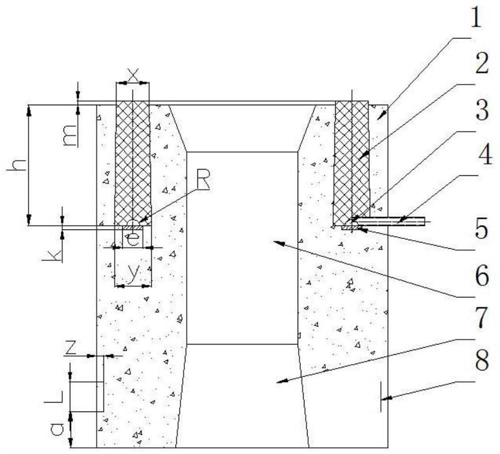
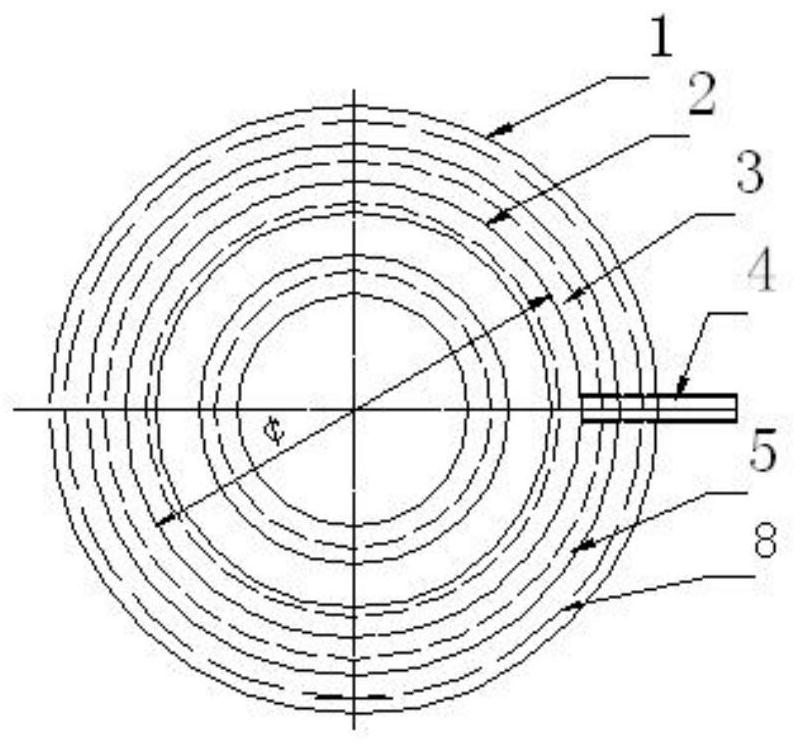
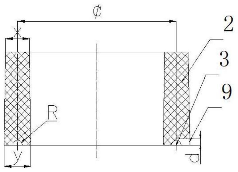
[0040] A kind of ladle argon blowing upper nozzle block, such as Figure 1-Figure 6 As shown, including the ladle argon blowing water nozzle base brick body 1, the diffuse vent ring 2, the air chamber 3, the air inlet pipe 4, the air chamber cover plate 5, the iron ring 8, the ladle argon blowing water nozzle base brick body 1 is set in the middle There are flow steel holes 6 and water inlet installation holes 7 through up and down. The ladle argon-blowing upper nozzle block body 1 is provided with a diffuse vent ring 2, an air chamber 3 and an air chamber cover 5 from top to bottom. The upper end of the air-permeable ring extends from the upper surface of the upper brick of the ladle argon-blown nozzle. The air chamber 3 is formed at the bottom of the diffuse air-permeable ring. The lower port of the air chamber 3 is provided with an air chamber cover 5, and one end of the air inlet pipe 4 is welded to The gas chamber cover plate 5 is connected to the gas chamber 3, and the ot...

Embodiment 2

[0057] The ladle argon blowing upper nozzle block as described in Example 1, the differences are:

[0058] The diffuse air-permeable ring 2 is a circular ring as a whole, and the longitudinal section is an isosceles trapezoid. The upper width x of the circular ring is 40 mm, the lower width y is 45 mm, and the height h is 160 mm.

[0059] The air chamber 3 has a circular ring shape as a whole, the longitudinal section of the air chamber is semicircular, and its radius R is 10 mm.

[0060] The air chamber cover plate 5 has a circular ring shape and a rectangular longitudinal section. The ring width e of the air chamber cover plate 5 is greater than the diameter 2R (20mm) of the air chamber 3, but smaller than the lower width y (45mm) of the gas chamber 3 ), e is 32mm.

[0061] The iron ring 8 is a circular ring as a whole, and the height L is 50mm. The distance a between the lower end of the iron ring and the lower end of the ladle argon blowing water nozzle base brick body 1 is 60mm, ...

Embodiment 3

[0069] The ladle argon blowing upper nozzle block as described in Example 1, the differences are:

[0070] The upper width x of the diffuse gas-permeable ring 2 is 30 mm, the lower width y is 40 mm, and the height h is 100 mm. The radius R of the longitudinal section of the air chamber 3 is 8 mm.

[0071] The air chamber cover plate 5 has a circular ring shape as a whole with a rectangular longitudinal section. The ring width e of the air chamber cover plate 5 is greater than the diameter 2R (16mm) of the air chamber 3, but is smaller than the lower width y (40mm) of the gas chamber 3 ), e is 30mm.

[0072] The iron ring 8 is a circular ring as a whole, and the height L is 45mm. The distance a between the lower end of the iron ring and the lower end of the ladle argon blowing water nozzle base brick body 1 is 55mm, and the iron ring 8 is embedded in the steel ladle argon blowing water nozzle base brick body. The inner depth z of the surface layer is 15mm.

[0073] The height m of th...


PUM

PropertyMeasurementUnit
Thicknessaaaaaaaaaa
High temperature compressive strengthaaaaaaaaaa
Bulk densityaaaaaaaaaa

Abstract

The invention relates to a steel ladle argon blowing upper water gap brick cup and a preparation method thereof. The steel ladle argon blowing upper water gap brick cup comprises a steel ladle argon blowing upper water gap brick cup body, a diffused ventilation ring, a gas chamber, a gas inlet pipe, a gas chamber cover plate and an iron ring. A steel flowing hole and an upper water gap mounting hole which are through up and down are formed in the middle of the steel ladle argon blowing upper water gap brick cup body. The diffused ventilation ring, the gas chamber and the gas chamber cover plate are arranged in the steel ladle argon blowing upper water gap brick cup body from top to bottom. The upper end of the diffused ventilation ring stretches out of the upper surface of the steel ladleargon blowing upper water gap brick cup body. The gas chamber is formed at the bottom of the diffused ventilation ring. The gas chamber cover plate is arranged on a lower opening of the gas chamber. One end of the gas inlet pipe is welded to the gas chamber cover plate and communicates with the gas chamber, and the other end of the gas inlet pipe stretches from the side of the steel ladle argon blowing upper water gap brick cup body. The up-and-down inversion method is adopted in pouring construction moulding bed assembling and pouring construction for preparing a steel ladle argon blowing upper water gap brick, and the technical problem that the diffused ventilation ring cannot be fixed easily is solved.

Description

Technical field [0001] The invention relates to a ladle argon blowing upper nozzle base brick and a preparation method thereof, and belongs to the technical field of steelmaking in iron and steel metallurgy. Background technique [0002] Argon blowing at the bottom of LF refining ladle is a simple and efficient refining technology outside the furnace. It is generally divided into two stages: large flow argon blowing and mixing in the early stage and low flow soft blowing to remove inclusions in the later stage. At present, two bottom-blown air-permeable bricks are generally used for domestic LF refined ladle of more than 100 tons. The processing time of high-quality steel is generally more than 40 minutes, of which the soft blowing is 8-12 minutes. The following problems or deficiencies exist in production practice at present: (1 ) Insufficient soft blowing time affects the removal effect of inclusions; (2) Too long LF refining time causes mismatch of furnace and machine, which b...

Claims


Application Information

Patent Timeline
IPC IPC(8): B22D41/58C21C7/072
CPCB22D41/58C21C7/072
Inventor 武光君王中学王建石磊张海波赵立峰
Owner LAIWU STEEL YINSHAN SECTION CO LTD
Learn More