
Spherical array sound source direction-of-arrival estimation method based on atomic norm

A direction of arrival estimation, spherical array technology, applied to systems for determining direction or offset, direction finders using ultrasonic/sonic/infrasonic waves, etc., can solve problems such as failure

Pending Publication Date: 2020-10-23
CHONGQING UNIV
View PDF0 Cites 4 Cited by
  • Summary
  • Abstract
  • Description
  • Claims
  • Application Information

AI Technical Summary

Problems solved by technology

However, the forward and reverse averaging method is only applicable to the case where the number of coherent sound sources is 2, and the frequency smoothing technique is only applicable to the case where the sound source radiates broadband signals
[0004] In summary, the shortcomings of spherical ESPRIT for high-frequency sound sources, coherent sound sources, few data snapshots or low SNR conditions are still unresolved

Method used


Image

  • Spherical array sound source direction-of-arrival estimation method based on atomic norm
  • Spherical array sound source direction-of-arrival estimation method based on atomic norm
  • Spherical array sound source direction-of-arrival estimation method based on atomic norm

Examples


Embodiment 1

[0190] see Figure 1 to Figure 9 , a direction-of-arrival estimation method for a spherical array sound source based on the atomic norm, including the following steps:

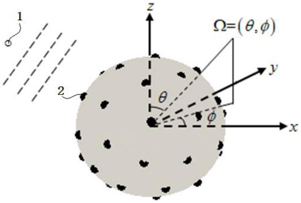
[0191] 1) Build a spherical microphone array composed of Q microphones 2 . The center of the spherical microphone array is recorded as the coordinate origin. Among them, the position of the qth microphone is recorded as (a,Ω Mq ). a is the array radius, q=1,2,...,Q. Ω=(θ,φ) represents any direction in the three-dimensional space where the spherical microphone array is located. θ∈[0°,180°] is the elevation angle, φ∈[0°,360°) is the azimuth angle. attached figure 1 "●" and "○" represent the microphone and the sound source respectively.

[0192] represents the set of real numbers, represents the set of positive real numbers, Represents a set of complex numbers, vectors are represented by bold lowercase letters, matrices are represented by bold uppercase letters, and the superscript " ★ "Indicates me...

Embodiment 2

[0310] Verification experiment of DOA estimation method for spherical array sound source based on atomic norm:

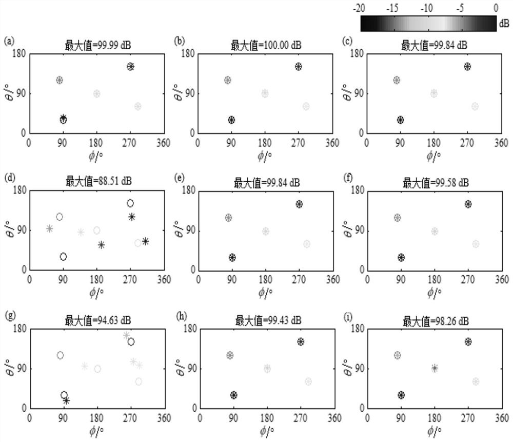
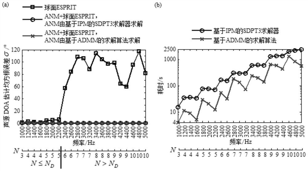
[0311] Carry out sound source identification simulation simulation. Five sound sources are assumed, and the DOAs are (30°, 90°), (150°, 270°), (120°, 80°), (60°, 290°) and (90°, 180°), strength They are 100dB, 97.5dB, 95dB, 92.5dB and 90dB in turn (reference 2×10⁻⁵Pa). The company's rigid ball array containing 36 microphones with a radius of 0.0975m is adopted, corresponding to N D for 5. When simulating the forward sound field, since infinite items cannot be calculated, N 0 Take it as 20. When using the ADMM-based algorithm to solve the equivalent semi-positive definite programming of ANM shown in formula (22), the relevant parameters are set as follows: ρ is set to 1, and τ is according to the literature "Off-the-grid line spectrum denoising and estimation with multiple measurement vectors", Y.Li, Y.Chi. IEEE Transactions on Signal Processing, volume64, is...


PUM


Abstract

The invention discloses a spherical array sound source direction-of-arrival estimation method based on an atomic norm. The method comprises the following steps that (1) a spherical microphone (2) array composed of Q microphones (2) is constructed; (2) a sound source (1) radiates sound waves to the spherical microphone (2) array; (3) a sound source direction-of-arrival measurement model is established, and a sound pressure signal matrix P<five-pointed star> measured by the microphone (2) is constructed; (4) a covariance matrix GTb(u^)G<H> is established; and (5) the covariance matrix GTb(u^)G<H> is resolved by using a spherical ESPRIT algorithm to determine the direction of arrival of the sound source. According to the method, the defect that the spherical ESPRIT fails under the high-frequency, coherent sound source or few-data snapshot working condition can be overcome, the DOA estimation precision of the sound source under the low SNR working condition is remarkably improved, and themethod is still effective even in a common test environment with reverberation.

Description

technical field [0001] The invention relates to the field of sound source identification, in particular to an atomic norm-based method for estimating the direction of arrival of a spherical array sound source. Background technique [0002] Direction-Of-Arrival (DOA) estimation of sound sources generally exists in the fields of noise source identification, target detection, fault diagnosis and so on. Estimation of Signal Parameters via Rotational Invariance Technique (ESPRIT) technology based on spherical microphone array measurement, referred to as spherical ESPRIT, has attracted much attention due to its advantages of panoramic estimation of sound source direction of arrival and low computational complexity. Spherical ESPRIT takes the covariance matrix of the array microphone measurement signal as input, and based on the recurrence relationship of spherical harmonics, transforms the DOA estimation problem of the sound source into a least square solution and eigenvalue decom...

Claims


Application Information

Patent Timeline
IPC IPC(8): G01S3/802
CPCG01S3/802
Inventor 褚志刚杨洋
Owner CHONGQING UNIV
Learn More