
Electronic brake device of electric vehicle and control algorithm of electronic brake device

A technology of electronic brakes and control algorithms, applied to bicycle accessories, transportation and packaging, bicycle brakes, etc., can solve problems such as safety hazards, abruptness, and bad driving experience

Pending Publication Date: 2020-10-23
苏州赤兔驱动科技有限公司
View PDF0 Cites 1 Cited by
  • Summary
  • Abstract
  • Description
  • Claims
  • Application Information

AI Technical Summary

Problems solved by technology

This may bring consumers a bad riding experience, and even bring danger
[0007] When the rider needs high-intensity braking, such as emergency braking, the electronic brake cannot provide enough braking force, so that the braking distance cannot be effectively shortened, and there are potential safety hazards
When the cyclist needs low-intensity braking, such as a small braking force to assist the vehicle to stop before the zebra crossing, if the electronic brake provides too much electromagnetic braking force, the cyclist suddenly feels a bad driving experience of "rushing"; and Abrupt and excessive electromagnetic braking force may also cause potential safety hazards under extreme conditions
The driving scene of the vehicle is very complex and changeable. At present, the simple circuit structure is easily affected by the electromagnetic radiation of the environment, and there is a risk of malfunction, which requires a good anti-interference design; and the brake is a high-frequency action device, which requires corresponding The redundant design ensures reliable operation within the life cycle, and when a failure occurs, the customer can be prompted, and in a short period of time, before maintenance, the use of the customer's electronic brake will not be affected
At present, the existing products do not have the above functions.

Method used


Image

  • Electronic brake device of electric vehicle and control algorithm of electronic brake device
  • Electronic brake device of electric vehicle and control algorithm of electronic brake device
  • Electronic brake device of electric vehicle and control algorithm of electronic brake device

Examples


Embodiment Construction

[0047] The specific implementation manners of the present invention will be further described in detail below in conjunction with the accompanying drawings and embodiments. The following examples are used to illustrate the present invention, but are not intended to limit the scope of the present invention.

[0048] In describing the present invention, it should be understood that the terms "center", "longitudinal", "transverse", "length", "width", "thickness", "upper", "lower", "front", " Orientation or position indicated by "back", "left", "right", "vertical", "horizontal", "top", "bottom", "inner", "outer", "clockwise", "counterclockwise", etc. The relationship is based on the orientation or positional relationship shown in the drawings, and is only for the convenience of describing the present invention and simplifying the description, rather than indicating or implying that the referred device or element must have a specific orientation, be constructed and operated in a sp...


PUM


Abstract

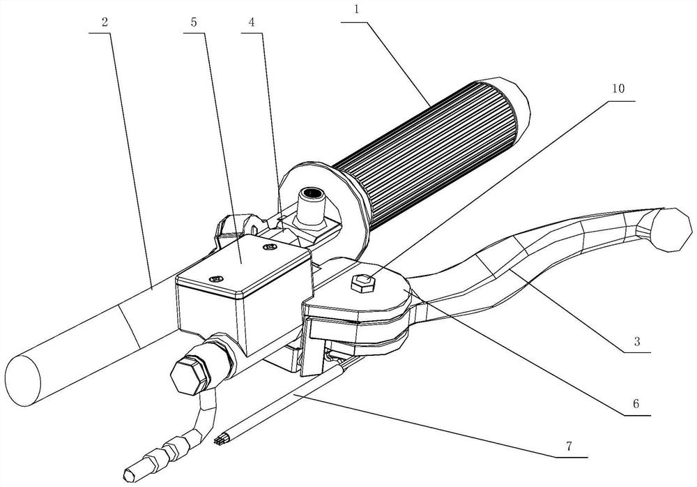
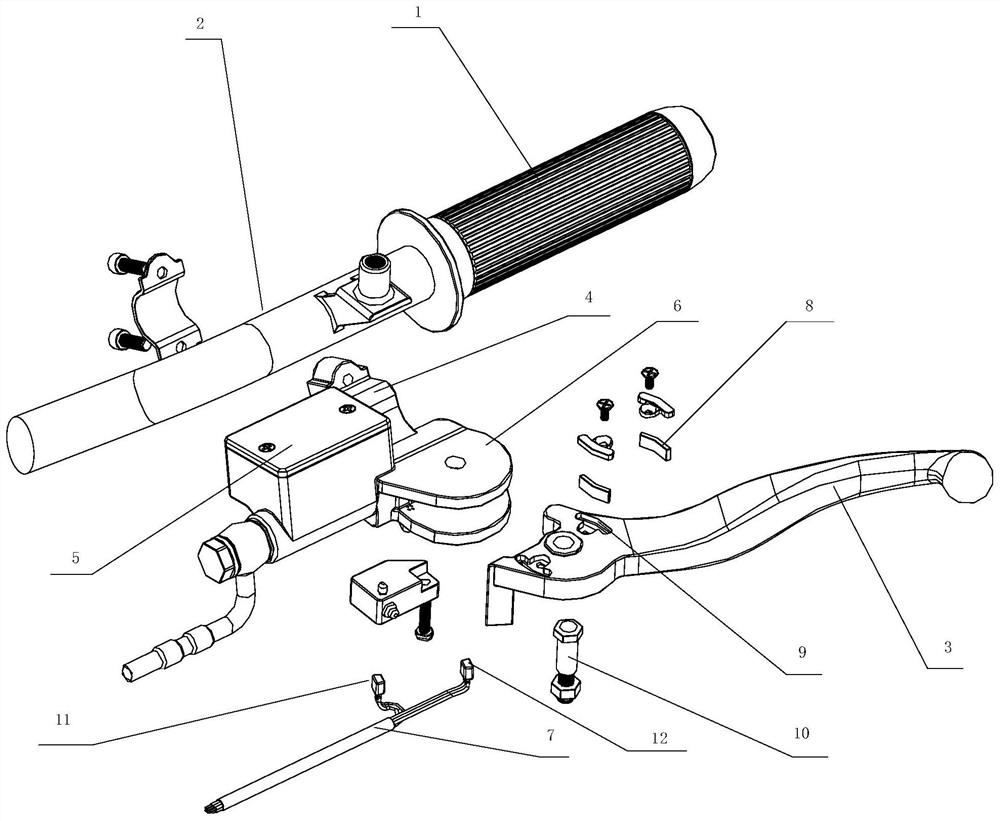
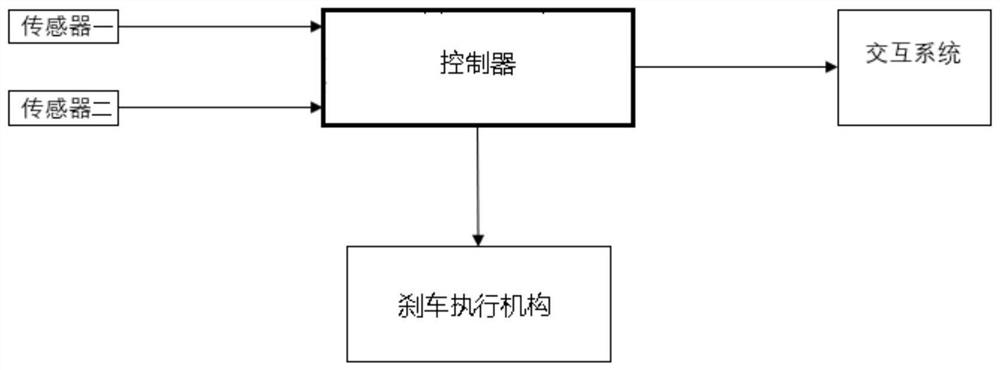
The invention relates to an electronic brake device of an electric vehicle. The device comprises a driving motor and a controller connected with the driving motor and used for controlling the drivingmotor to operate. The device further comprises a grip, a steering tube and a brake handle. The grip is connected with the steering tube; a connecting seat is arranged on the steering pipe, a brake support used for installing a brake hydraulic kettle is arranged on the connecting seat, the brake handle with the end capable of rotating relative to the brake support is further arranged on the brake support, a sensor set capable of sensing displacement of the end of the brake handle relative to the brake support is arranged on the brake support, and the controller is electrically connected with the sensor set. According to the control algorithm, the electronic brake device detects the brake stroke through the sensor set of the electronic brake device, the requirement for the brake strength isjudged based on the stroke length, and therefore the strength of an electronic brake is controlled. Required braking force can be output according to customer requirements, good riding experience is provided for a rider, hidden dangers and dangers are eliminated, influence of electromagnetic radiation on the environment can be effectively restrained, and reliable operation of the device is guaranteed.

Description

technical field [0001] The invention relates to the field of electric vehicles, in particular to an electric vehicle electronic braking device and a control algorithm thereof. Background technique [0002] At present, the existing electric vehicles are mainly braked by front and rear mechanical brakes. The mechanical brake method requires long-term friction of the brake pads, which leads to rapid wear of the brake pads. At the same time, during emergency braking, it is easy to lock and cause wrestling. If the brake pads If it is not replaced in time after wear and tear, it is prone to brake failure, resulting in personnel safety accidents. The electronic braking system of electric vehicles means that when the electronic control system detects mechanical braking, it turns the drive motor into a generator, thereby generating additional electromagnetic braking force through the generator current to assist and enhance the braking effect. [0003] The drive motor (also called dr...

Claims


Application Information

Patent Timeline
IPC IPC(8): B62L3/02B62J45/41B62J45/422
CPCB62L3/026B62J45/41B62J45/422
Inventor 吴道贤刘建城石飞雷吉
Owner 苏州赤兔驱动科技有限公司
Learn More