
LDMOS device and process method

A process method and device technology, applied in semiconductor devices, semiconductor/solid-state device manufacturing, electrical components, etc., can solve problems such as unsatisfactory breakdown voltage

Pending Publication Date: 2020-10-16
SHANGHAI HUAHONG GRACE SEMICON MFG CORP
View PDF12 Cites 2 Cited by
  • Summary
  • Abstract
  • Description
  • Claims
  • Application Information

AI Technical Summary

Problems solved by technology

[0004] The breakdown voltage BV or characteristic on-resistance R of the LDMOS devices with the above two structures SP Neither is ideal, and there is still room for further optimization

Method used


Image

  • LDMOS device and process method
  • LDMOS device and process method
  • LDMOS device and process method

Examples


Embodiment Construction

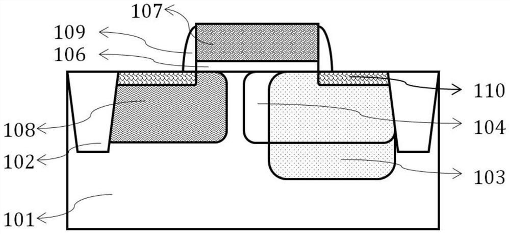
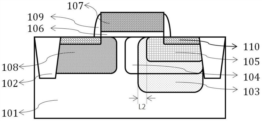
[0040]The technical solution of the present invention will be described in detail below. In the following embodiments, the present invention will take the most common and widely used N-type LDMOS device as an example, that is, the first conductivity type in this embodiment It is defined as P type, and the second conductivity type is defined as N type. In other opposite embodiments, the first conductivity type can be defined as N-type, and the second conductivity type can be defined as P-type, which can be directly replaced, and the present invention will not further elaborate on this.

[0041] A kind of LDMOS device described in the present invention, such as figure 2 As shown, there is a P-type body region 108 and an N-type drift region 104 in a P-type substrate or epitaxy 101;

[0042] There is also a polysilicon gate structure on the surface of the P-type substrate, and the polysilicon gate structure includes a gate dielectric layer 106, a polysilicon gate 107, and gate s...


PUM


Abstract

The invention discloses an LDMOS device. A body region and a drift region are arranged in a substrate or epitaxy; the body region comprises a heavily-doped region serving as a source region of the LDMOS device; a heavily-doped region is arranged in the drift region to serve as a drain region of the LDMOS device; a first well region and a second well region are further arranged in the drift region,the injection range of the first well region does not exceed the drift region, and the injection depth of the first well region is greater than that of the drift region; and the injection range of the second well region is smaller than that of the drift region. According to the invention, the first well region and the second well region are respectively completed by well injection of a low-voltage CMOS and well injection of a high-voltage CMOS synchronously; three times of superposition injection are formed at the drain end, the doping concentration of the drain end is improved, the characteristic on-resistance RSP of the device is reduced, and the breakdown voltage BV is improved. Based on the BCD process, an extra injection process is not needed when the first well region and the secondwell region are formed, and the process does not need to be changed.

Description

technical field [0001] The invention relates to the field of semiconductor integrated circuit manufacturing, in particular to an LDMOS device integrated in a BCD process. The invention also relates to the process method of the LDMOS device. Background technique [0002] DMOS (Double-diffused MOS) is currently widely used in power management chips due to its characteristics of high voltage resistance, high current drive capability and extremely low power consumption. In LDMOS (Lateral Double-diffused MOSFET, lateral double-diffused field effect transistor) devices, on-resistance is an important indicator. In the BCD (Bipolar-CMOS-DMOS) process, although LDMOS and CMOS are integrated in the same chip, due to the high breakdown voltage BV (Breakdown Voltage) and low characteristic on-resistance R SP There are contradictions / compromises between (Specific on-Resistance), which often cannot meet the requirements of switching tube applications. High-voltage LDMOS not only has th...

Claims


Application Information

Patent Timeline
Patent Type & Authority Applications(China)
IPC IPC(8): H01L21/336H01L29/08H01L29/78
CPCH01L29/66681H01L29/7816H01L29/0882
Inventor 许昭昭
Owner SHANGHAI HUAHONG GRACE SEMICON MFG CORP
Learn More