
Energy-saving transformer with high insulation heat-resistant grade and high overload

An energy-saving transformer, heat-resistant technology, applied in the direction of transformer/inductor housing, transformer/inductor cooling, transformer/inductor components, etc., can solve problems such as poor insulation effect, inability to use electricity independently, and no high temperature resistance. , to facilitate repair and maintenance, ensure stability, and improve the effect of heat resistance

Pending Publication Date: 2020-10-16
JIANGSU RYAN ELECTRIC LTD BY SHARE LTD
View PDF0 Cites 0 Cited by
  • Summary
  • Abstract
  • Description
  • Claims
  • Application Information

AI Technical Summary

Problems solved by technology

[0004] The purpose of the present invention is to provide an energy-saving transformer with high insulation and heat resistance level and high overload, which solves the problem that the existing general energy-saving transformer has poor insulation effect and no high temperature resistance effect, and cannot make full use of external energy during use. At the same time, there is the problem that the internal power consumption of the device cannot be independent, so there is a problem of inconvenient power consumption when the energy-saving transformer is damaged.

Method used


Image

  • Energy-saving transformer with high insulation heat-resistant grade and high overload
  • Energy-saving transformer with high insulation heat-resistant grade and high overload
  • Energy-saving transformer with high insulation heat-resistant grade and high overload

Examples


Embodiment Construction

[0029] The following will clearly and completely describe the technical solutions in the embodiments of the present invention with reference to the accompanying drawings in the embodiments of the present invention. Obviously, the described embodiments are only some, not all, embodiments of the present invention. Based on the embodiments of the present invention, all other embodiments obtained by persons of ordinary skill in the art without making creative efforts belong to the protection scope of the present invention.

[0030] In the description of the present invention, unless otherwise stated, the meaning of "plurality" is two or more; the terms "upper", "lower", "left", "right", "inner", "outer" , "front end", "rear end", "head", "tail", etc. indicate the orientation or positional relationship based on the orientation or positional relationship shown in the drawings, and are only for the convenience of describing the present invention and simplifying the description, rather...


PUM


Abstract

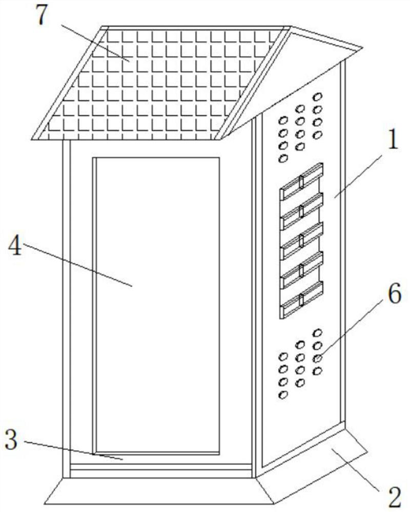
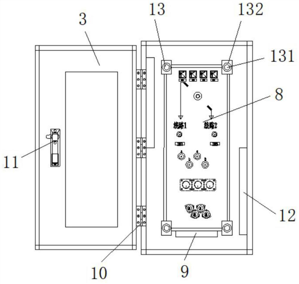
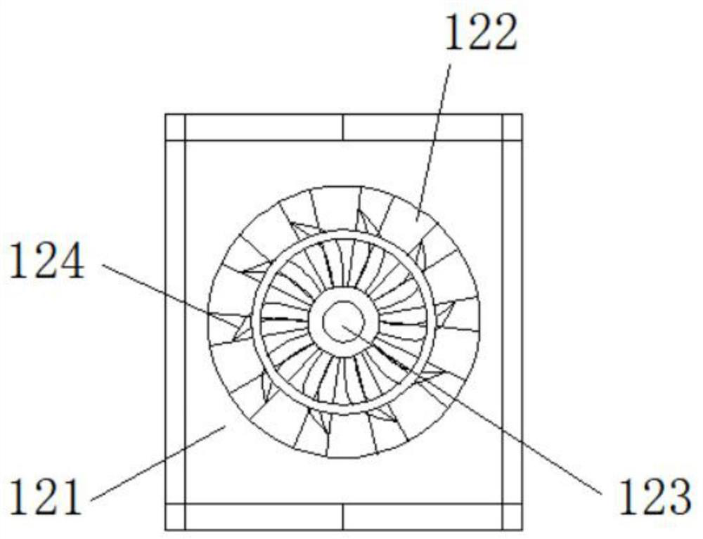
The invention discloses an energy-saving transformer with a high insulation heat-resistant grade and high overload. The energy-saving transformer comprises an energy-saving transformer shell, a shielding structure, a high heat dissipation structure, a transformer insulation assembly structure and a wiring harness protection connection structure, and a pouring base is fixed to the bottom end of theenergy-saving transformer shell. A sealing cover plate is arranged on the front end face of the energy-saving transformer shell, the transformer insulation assembly structure is arranged at the rearend of the energy-saving transformer body, the high heat dissipation structures are installed on the inner end faces of the left side and the right side of the energy-saving transformer shell, and thewiring harness protection connection structure is arranged on the rear end face of the energy-saving transformer shell. By arranging the shielding structure, the sun-shading and rain-proof effects can be achieved on the whole device at the top end of the device, solar energy can be absorbed through the arranged solar cell panel and converted into electric energy to be used, and therefore electricpower used in the device can be independent, and the situation that the electric power used by the device is affected by the quality of a transformer is avoided.

Description

technical field [0001] The invention relates to the technical field of energy-saving transformers, in particular to an energy-saving transformer with high insulation and heat resistance and high overload. Background technique [0002] Transformer refers to a device that uses the principle of electromagnetic induction to change AC voltage. Its main components are primary coil, secondary coil and iron core (magnetic core). The main functions of transformers are: voltage conversion, current conversion, impedance conversion, isolation, voltage stabilization (magnetic saturation transformer), etc., and can be divided into power transformers and special transformers according to their uses. The most basic form of a transformer consists of two coils wound with wire and connected together inductively. When an alternating current (with a known frequency) flows in one of the coils, an alternating voltage with the same frequency will be induced in the other coil, and the magnitude of ...

Claims


Application Information

Patent Timeline
IPC IPC(8): H01F27/02H01F27/08H01F27/40H02J7/35
CPCH01F27/022H01F27/025H01F27/08H01F27/40H02J7/35Y02A30/14
Inventor 王良明王军强乔红军徐伟梅德进
Owner JIANGSU RYAN ELECTRIC LTD BY SHARE LTD
Learn More