
Multifunctional bridge frame punching mould

A stamping die and multi-functional technology, applied in the field of multi-functional bridge stamping dies, can solve the problems of profile transfer and long processing time, affect processing efficiency, and high debugging requirements, so as to improve stable batch production, improve processing efficiency, and avoid process transfer Effect

Pending Publication Date: 2020-10-16
镇江市诚邦机械制造有限公司
View PDF0 Cites 2 Cited by
  • Summary
  • Abstract
  • Description
  • Claims
  • Application Information

AI Technical Summary

Problems solved by technology

Without increasing the wall thickness of the bridge, the stress of the bridge can be eliminated by punching the ribs on the bridge profile, and the strength and load of the bridge profile can be increased. During the processing of the C-shaped bridge, it is also necessary to punch out the connection hole with the cover plate, Horizontal hanging holes, connecting holes and nameplate stamps, etc., the bridge needs to be processed by stamping machines or corresponding molds for many times. Since the bridge profile sheet metal is long, it needs to be cut to length after stamping, so that it can be bent and other processing and manufacturing. Obtaining a fixed-length C-shaped or other-shaped bridge frame will result in a larger space occupied by the equipment line, higher equipment investment costs, longer profile transfer and processing time, which will affect the processing efficiency. At the same time, for different specifications or differences in punching positions Different batches of bridge processing requirements require frequent replacement or adjustment of the position of the corresponding mold and stamping program, which requires high debugging, thus increasing production costs, low processing efficiency of bridges, and difficulty in meeting the production needs of bridges of various specifications, which needs to be improved urgently

Method used


Image

  • Multifunctional bridge frame punching mould
  • Multifunctional bridge frame punching mould
  • Multifunctional bridge frame punching mould

Examples


Embodiment Construction

[0050] The specific embodiments of the present invention will be further described below in conjunction with the accompanying drawings.

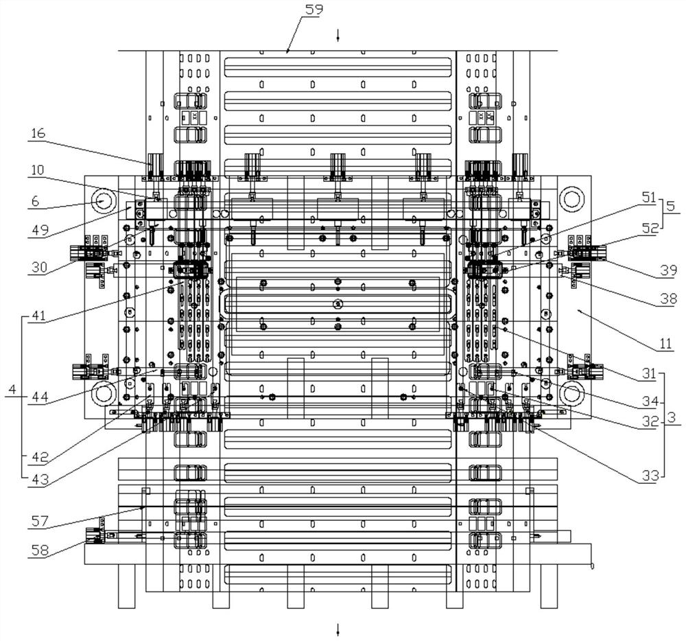
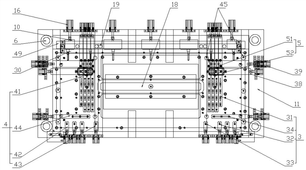
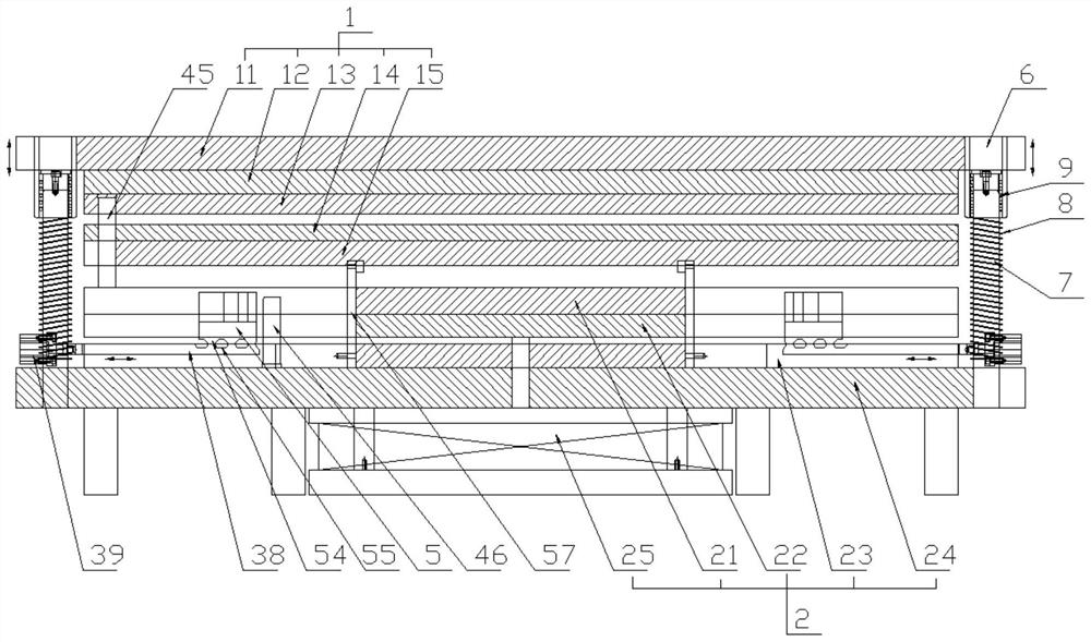
[0051] A multifunctional bridge stamping die, comprising an upper die 1 and a lower die 2 that can be opened and closed vertically, wherein the upper die 1 includes an upper die base 11, an upper backing plate 12, an upper die set sequentially from top to bottom. Clamping plate 13, stopper plate 14 and stripping plate 15, said lower mold 2 includes lower template 21, lower backing plate 22, lower splint 23, lower bottom plate 24 and lower mold base 25 arranged in sequence from top to bottom;

[0052] Both sides of the upper mold base 11 are provided with a first guide hole 6, and the lower bottom plate 24 is provided with a first guide post 7 corresponding to the first guide hole 6, and the first guide post 7 is provided with a The first spring 8, the first guide hole 6 is provided with a ball guide bushing 9 at the top of the first spring 8...


PUM


Abstract

The invention relates to a multifunctional bridge frame punching mould which comprises an upper mould body and a lower mould body. The upper mould body and the lower mould body can be opened and closed vertically. The upper mould body comprises an upper mould base, an upper cushion plate, an upper clamping plate, a stop plate and a stripping plate. The lower mould body comprises a lower mould plate, a lower cushion plate, a lower clamping plate, a lower bottom plate and a lower mould base. A plurality of first pulling blocks and second pulling blocks are arranged between the upper mould base and the upper cushion plate and linearly move on the horizontal plane. The upper clamping plate is provided with an upper cutter capable of lifting and floating, and a plurality of punching heads. A concave mould is arranged on the bottom of the stripping plate. The lower mould plate is provided with a convex mould and a cutter drawing plate. Lower mould blocks capable of lifting and floating are arranged in the lower mould plate and the lower cushion plate. A plurality of third pulling blocks are arranged on the bottoms of the lower mould blocks and move linearly on the horizontal plane. In one working procedure, continuous machining forming and fixed-length cutting can be carried out on different specifications of plates with different hole positions, hole types, punching positions, bottom ribs, square ribs, trade mark shapes, positions and structure bridge frame types, cost and equipment space are reduced remarkably, the production efficiency is improved, and the requirements for batch production of multiple bridge frames can be met.

Description

technical field [0001] The invention relates to a multifunctional bridge stamping die, which belongs to the technical field of bridge production equipment. Background technique [0002] Cable trays are divided into trough cable trays, tray cable trays, stepped cable trays, and grid trays. They are composed of brackets, brackets, and installation accessories. It is widely used in cable laying engineering on the support of the gallery. Without increasing the wall thickness of the bridge, the stress of the bridge can be eliminated by punching the ribs on the bridge profile, and the strength and load of the bridge profile can be increased. During the processing of the C-shaped bridge, it is also necessary to punch out the connection hole with the cover plate, Horizontal hanging holes, connecting holes and nameplate stamps, etc., the bridge needs to be processed by stamping machines or corresponding molds for many times. Since the bridge profile sheet metal is long, it needs to ...

Claims


Application Information

Patent Timeline
Patent Type & Authority Applications(China)
IPC IPC(8): B21D37/10B21D37/12B21D35/00B21D22/02B21D28/34B21D28/14B21D28/02
CPCB21D37/10B21D37/12B21D35/001B21D22/02B21D28/34B21D28/14B21D28/02
Inventor 时进专
Owner 镇江市诚邦机械制造有限公司
Learn More