
Laser radar detection system and laser radar detection method

A technology of lidar and detection system, applied in the field of lidar detection system and lidar detection, can solve problems such as difficulty in obtaining vertical resolution, difficulty in assembly adjustment, detection impact, etc., to ensure scanning range, comprehensive scanning range and detection accuracy high effect

Pending Publication Date: 2020-10-13
NINGBO SUNNY AUTOMOTIVE OPTECH
View PDF0 Cites 1 Cited by
  • Summary
  • Abstract
  • Description
  • Claims
  • Application Information

AI Technical Summary

Problems solved by technology

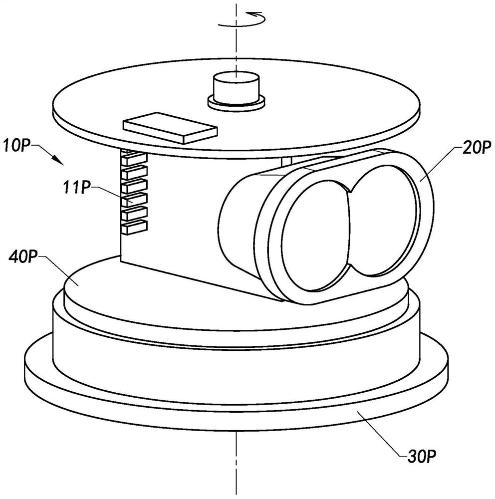
Therefore, the assembly and adjustment of each component is difficult. The scanning element 10P and the receiving unit 20P need to rotate together, and the volume cannot be controlled. It is necessary to ensure a certain volume so as not to affect the detection.
However, the scanning element 10P and the receiving unit 20P rotate together, which puts a heavy load on the rotating mechanism 40P, resulting in greater power consumption.
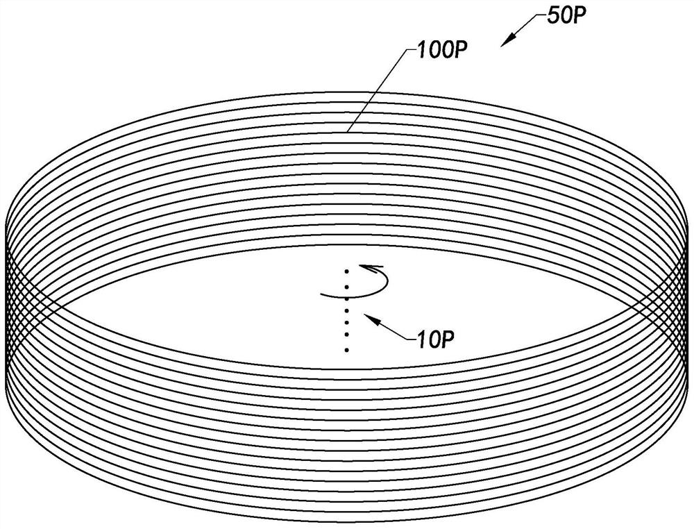
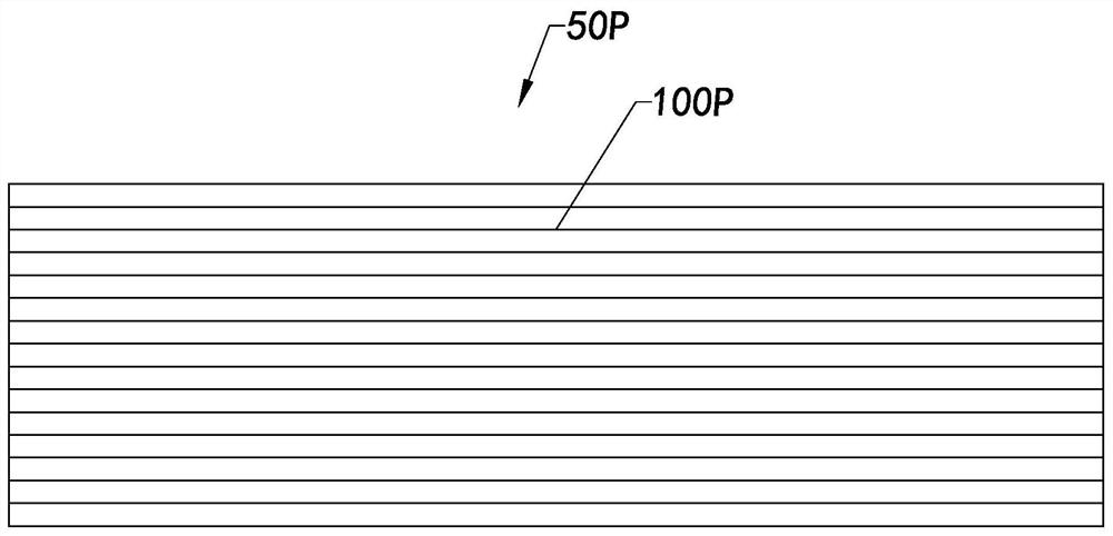
The height of the transmitter module is limited by the height of the components and cannot be made very small, and it is difficult to increase the number of lines per unit height, so it is difficult to obtain a higher vertical resolution
[0009] The multi-line laser radar detection system with a large volume cannot be well adapted to the small space constraints of vehicles, and there are many rotating parts, and the stability will also be affected when it is applied on vehicles

Method used


Image

  • Laser radar detection system and laser radar detection method
  • Laser radar detection system and laser radar detection method
  • Laser radar detection system and laser radar detection method

Examples


Embodiment Construction

[0065] The following description serves to disclose the present invention to enable those skilled in the art to carry out the present invention. The preferred embodiments described below are only examples, and those skilled in the art can devise other obvious variations. The basic principles of the present invention defined in the following description can be applied to other embodiments, variations, improvements, equivalents and other technical solutions without departing from the spirit and scope of the present invention.

[0066] Those skilled in the art should understand that in the disclosure of the present invention, the terms "vertical", "transverse", "upper", "lower", "front", "rear", "left", "right", " The orientation or positional relationship indicated by "vertical", "horizontal", "top", "bottom", "inner", "outer", etc. is based on the orientation or positional relationship shown in the drawings, which are only for the convenience of describing the present invention...


PUM


Abstract

The invention provides a laser radar detection system and a laser radar detection method. The laser radar detection system comprises a scanning unit and a receiving unit, the scanning element comprises a light source and a first reflection element. Light beams emitted by the light source, the first reflecting element is arranged on the emergent side of the light source; the first reflecting element is driven to rotationally reflect the light beam projected by the light source to a target area; the light beam is projected to the target area and moves in the target region as the first reflectiveelement rotates so as to scan the target area, and after the scanning unit emits a light beam to the target area, the receiving unit is used for receiving the light beam which is reflected by the target area after the scanning unit emits the light beam to the target area and detecting the target area.

Description

technical field [0001] The invention relates to the field of optics, in particular to a laser radar detection system and a laser radar detection method. Background technique [0002] The laser radar system emits laser light to the target area through the laser, and the target area reflects the light beam for the detector to receive. The light beam reflected by the target area carries image information, and the detector receives the light beam and information to realize the detection of the target area. [0003] Compared with the single-line radar, the multi-line lidar system can obtain more information, detect a wider range, and have higher accuracy. [0004] Such as Figure 1A Shown is an existing multi-line laser radar system, the multi-line laser radar system includes a scanning unit 10P and a receiving unit 20P, the scanning unit 10P includes a laser 11P, and the laser 11P emits a beam. The multi-line laser radar system also includes a base 30P and a rotating mechanism...

Claims


Application Information

Patent Timeline
Patent Type & Authority Applications(China)
IPC IPC(8): G01S17/02G01S7/481
CPCG01S17/02G01S7/4811
Inventor 尹骁徐超杨佳张绍鹏叶鑫源
Owner NINGBO SUNNY AUTOMOTIVE OPTECH
Learn More