
Millimeter wave cloud wireless access network beam design method based on secure transmission

A technology of wireless access network and design method, which is applied in the field of network transmission and can solve problems such as artificial noise

Active Publication Date: 2020-10-09
ZHENGZHOU UNIV +1
View PDF7 Cites 6 Cited by
  • Summary
  • Abstract
  • Description
  • Claims
  • Application Information

AI Technical Summary

Problems solved by technology

Although there are many design schemes for PLS, there are still some other challenges, such as hybrid analog / digital beamforming (Beamforming, BF) design, artificial noise, multicast BF design, etc.

Method used


Image

  • Millimeter wave cloud wireless access network beam design method based on secure transmission
  • Millimeter wave cloud wireless access network beam design method based on secure transmission
  • Millimeter wave cloud wireless access network beam design method based on secure transmission

Examples


Embodiment 1

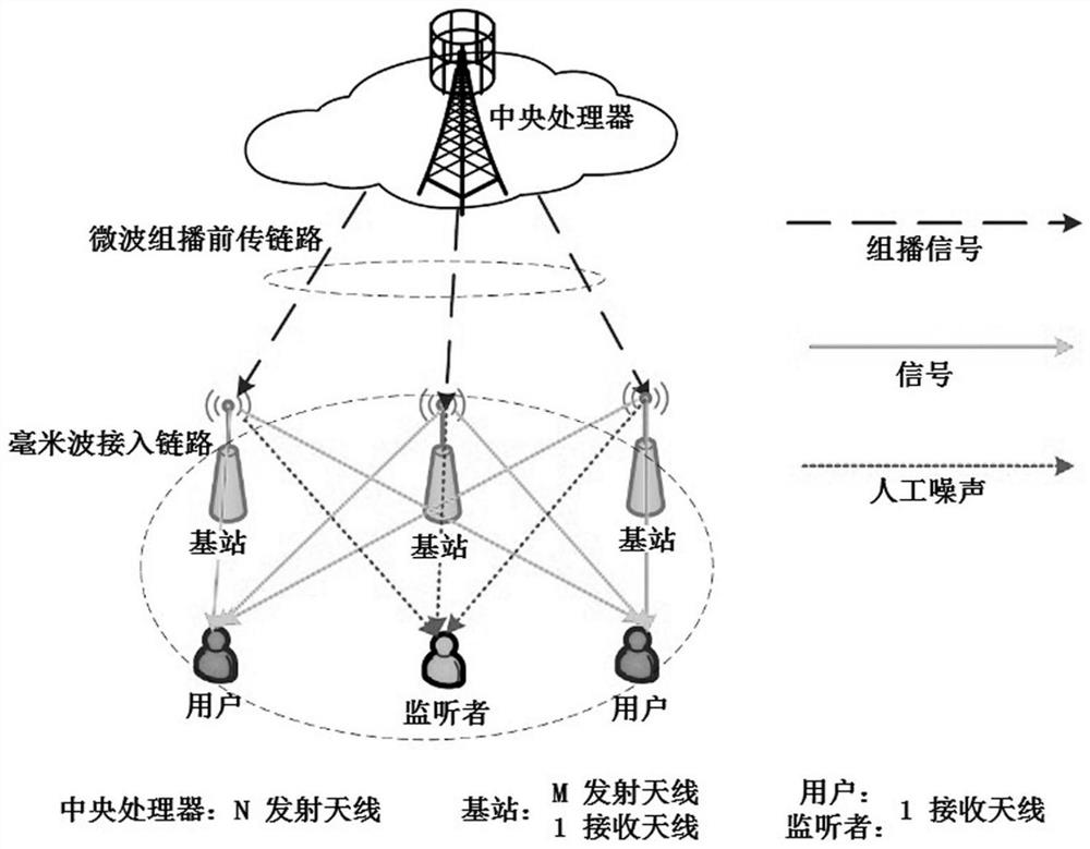
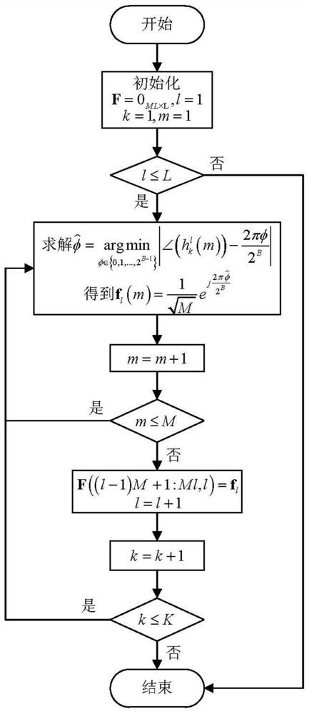
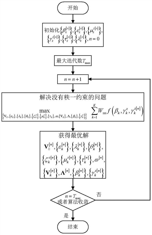
[0126] Embodiment 1: as Figure 1-Figure 6 As shown, the design of the present invention is under a C-RAN downlink system that relies on the central CP, and the system diagram is shown in the attached figure 1 As shown, the system consists of L cooperative base stations to form a base station cluster, in which all base stations jointly provide services for K single-antenna users through cooperative millimeter-wave BF. We assume that there are Z single-antenna Eves that may eavesdrop on user messages. The CP equipped with N antennas first sends the information required by the user to the base station through the microwave multicast forward link, and each base station is equipped with a single RA and M TAs. Suppose one RF serves M TAs through a set of phase shifters. Concrete inventive steps are as follows:

[0127] The first step: system model establishment

[0128] In the microwave multicast forward link, the forward link channel vector from the CP to the lth base station i...


PUM


Abstract

The invention relates to the field of network transmission, in particular to a millimeter wave cloud wireless access network beam design method based on secure transmission, which comprises the following steps of: 1, establishing a system model, 2, designing an analog beam, and 3, solving a secrecy rate transmission problem. Through the design of each step, the confidentiality rate of informationtransmission is maximized.

Description

technical field [0001] The present invention relates to the field of network transmission, in particular to a method for designing a beam of a millimeter wave cloud wireless access network based on secure transmission. Background technique [0002] With the rapid increase of mobile Internet services, various mobile applications have higher and higher data rate requirements, and cloud radio access network (Cloud radio access network, C-RAN) technology is proposed as an effective solution. In the C-RAN, a central processor (Central processor, CP) uses global channel state information (Channel state information, CSI) to perform resource optimization configuration, which improves the spectral efficiency (Spectral efficiency, SE) of the system. In addition, with the deployment of ultra-dense base stations, the interference between base stations can be effectively resolved through coordinated multiple-point (CoMP) technology, that is, using adjacent base stations to form base stat...

Claims


Application Information

Patent Timeline
Patent Type & Authority Applications(China)
IPC IPC(8): H04B7/06H04B7/024H04B7/0426H04W4/06H04W52/14H04W52/26H04W52/32H04W52/34H04W52/42H04W72/04H04W72/08H04W72/54
CPCH04B7/0617H04B7/024H04B7/0426H04W4/06H04W52/143H04W52/267H04W52/327H04W52/34H04W52/42H04W72/0473H04W72/542
Inventor 郝万明赵少柯孙钢灿赵飞
Owner ZHENGZHOU UNIV
Learn More