


Quick Research
Generate reliable direction feasibility study reports for your R&D in just a few steps.

Technical Q&A
Discover and master advanced knowledge NOW. Basics, ideas, possibilities, all at once.

Find Solutions
As an expert in R&D theories, this can generate solutions to your technical problems instantly.

Evaluate Feasibility
Analyze your overall solution with one click, know your potential R&D risks in advance.

Monitor Landscape
Get weekly tech updates, stay abreast of the latest tech innovations and key insights.
A method of manufacturing chain rigging with carbon fiber composite material
A composite material and carbon fiber technology, applied in the field of traction rigging, can solve problems such as poor fatigue resistance and reduced elongation, and achieve the effects of good permeability, low-cost manufacturing, and light weight
- Summary
- Abstract
- Description
- Claims
- Application Information
AI Technical Summary
Problems solved by technology
Method used
Image

Examples
specific Embodiment approach 1
[0062] Specific implementation mode one: as Figure 1-8 , Figure 11-Figure 14 As shown, this embodiment discloses a method for manufacturing chain slings with carbon fiber composite materials, and the steps of the method are as follows:
[0063] 1. A method for manufacturing chain slings with carbon fiber composite materials, characterized in that: the method steps are as follows:
[0064] Step 1: Chain one-ring forming scheme
[0065] 1.1 Forming
[0066] Assume that the diameter of the preformed chain sling is D, and use the automatic winding equipment (for the existing equipment) to pass the narrow strip of carbon fiber prepreg with a width of 15-29% D through the heating tube to raise the temperature at 35-145°C and add 1-10kg in reverse Tighten the narrow strip of carbon fiber prepreg, wrap it hoop-wise on the winding boss-5 of the chain-ring forming tooling, and wrap it hoop-wise to a diameter of 80-99% D to form a chain-ring blank;
[0067] 1.2 Profile
[0068] Ta...
specific Embodiment approach 2
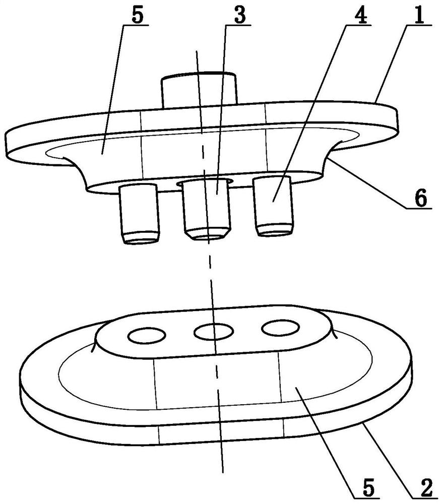
[0079] Specific implementation mode two: as figure 1 As shown, a method for manufacturing chain slings with carbon fiber composite materials described in Embodiment 1, in the 1.1 molding of step 1, the chain-ring forming tooling includes a chain-ring forming tooling upper mold 1, a chain-ring Forming tooling lower die 2, positioning pin 13 and two screws 14; said chain one-ring forming tooling upper die 1 lower end middle part and chain one ring forming tooling lower die 2 upper end middle part are all provided with winding boss 15, two The shape and size of the two winding bosses-5 are consistent, the outer contours of the two winding bosses-5 are consistent with the shape of the inner ring surface of the preformed chain ring (for winding the chain ring), and the two winding bosses-1 The outer contour line 6 of 5 is a 1 / 4 circle, and the height of each winding boss 5 is 1 / 2D. The middle part of the upper mold 1 of the chain forming tooling runs through the thickness of the wi...
specific Embodiment approach 3
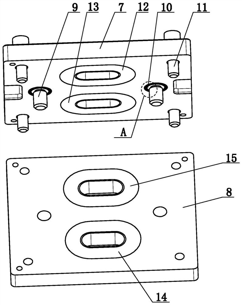
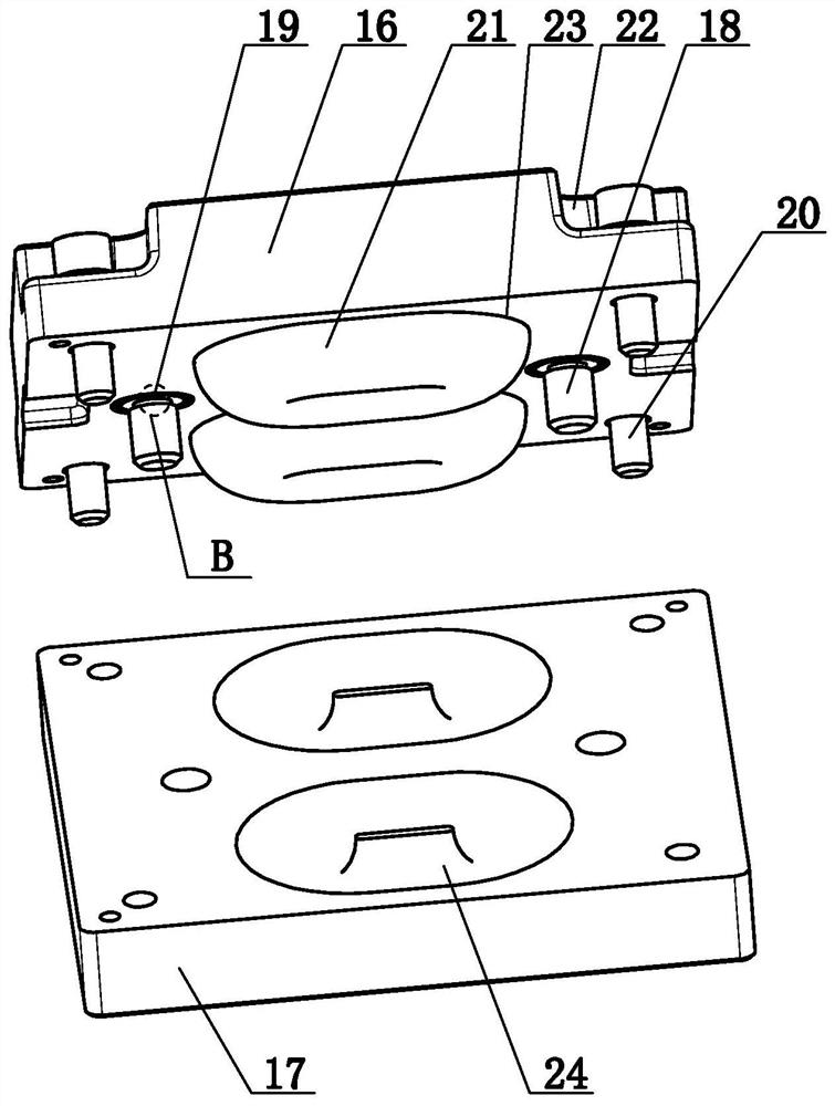
[0080] Specific implementation mode three: as figure 2 , Figure 11 As shown, in the method for manufacturing chain slings with carbon fiber composite materials described in Embodiment 1, in the 1.2 molding of step 1, the chain-ring stamping tooling includes a chain-ring stamping tooling upper die 7, a chain-ring stamping tooling Ring stamping tooling lower die 8, at least two positioning pins 29, at least two bushings 10 and at least four screws 211; the chain one ring stamping tooling upper die 7 and chain one ring stamping tooling lower die 8 appearance Both are cuboids, the lower surface of the chain one-ring stamping tooling upper die 7 is provided with at least one chain one-ring pressing die cavity one 12 and at least one chain one-ring pressing die cavity two 13, and the chain one ring stamping tooling lower die 8 The upper surface is provided with at least one chain-ring pressing die cavity one 14 and at least one chain-ring pressing die cavity two 15, and all of th...
PUM
| Property | Measurement | Unit |
|---|---|---|
| density | aaaaa | aaaaa |
| density | aaaaa | aaaaa |
| length | aaaaa | aaaaa |
Abstract
Description
Claims
Application Information
 - R&D Engineer
- R&D Manager
- IP Professional
- Industry Leading Data Capabilities
- Powerful AI technology
- Patent DNA Extraction
Browse by: Latest US Patents, China's latest patents, Technical Efficacy Thesaurus, Application Domain, Technology Topic, Popular Technical Reports.
© 2024 PatSnap. All rights reserved.Legal|Privacy policy|Modern Slavery Act Transparency Statement|Sitemap|About US| Contact US: help@patsnap.com