Groove punching device for metal dust covers of automatic deep groove ball bearing
A technology for deep groove ball bearings and dust covers, which is applied in the field of pressure grooving devices, can solve problems such as inability to process dust covers, and achieve the effects of small size, convenient use, and improved safety
- Summary
- Abstract
- Description
- Claims
- Application Information
AI Technical Summary
Problems solved by technology
Method used
Image
Examples
Embodiment 1
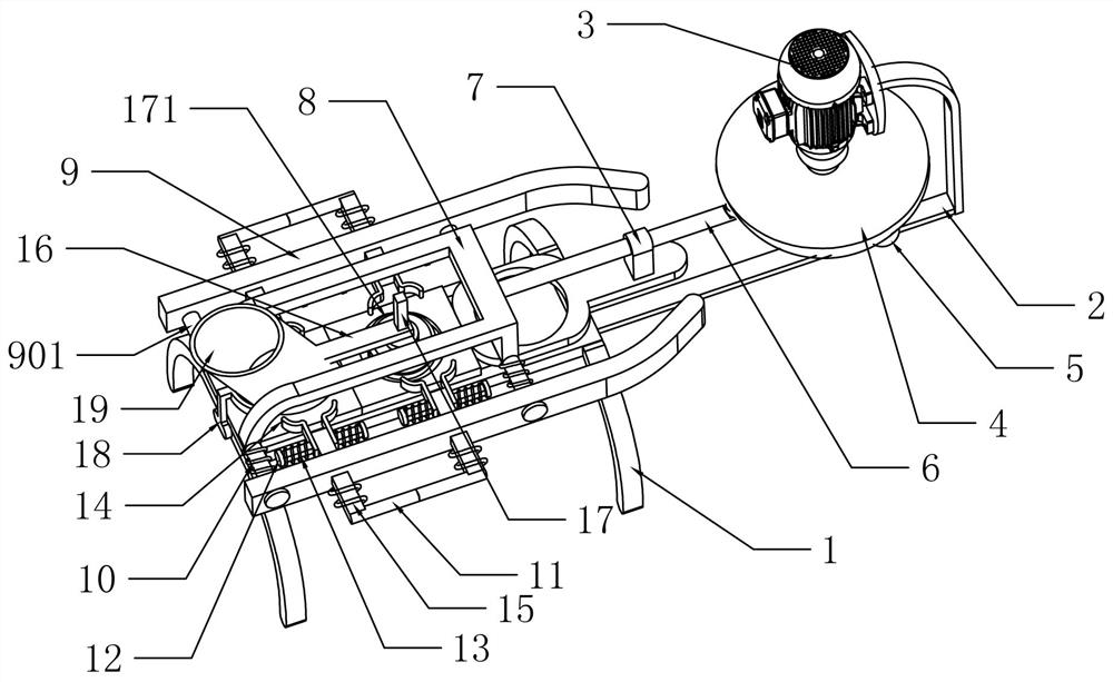
[0055] An automatic deep groove ball bearing metal dust cover pressing groove device, such as Figure 1-2 As shown, it includes a frame 1, a support plate 2, a left and right moving mechanism, a clamping mechanism, a fixed frame 18, a barrel 19 and a pressure groove mechanism. The right side is affixed with support plate 2, frame 1 and support plate 2 are provided with left and right movement mechanism, and left and right movement mechanism is provided with clamping mechanism, and frame 1 left side is affixed with fixed frame 18, and fixed frame 18 right end is fixed. Connected with material barrel 19, the pressure groove mechanism is positioned at frame 1 forming pressure groove top and is connected with material barrel 19 and left and right moving mechanism.
[0056] During work, metal sheet is put in the full feed bucket 19, leaves gap between feed bucket 19 and frame 1, and its gap is the same as metal sheet thickness, and metal sheet falls on the slideway of frame 1 from ...
Embodiment 2
[0058] On the basis of Example 1, such as figure 2 and Figure 4 As shown, the left and right moving mechanism includes a servo motor 3, a turntable 4, a rocker arm 5, a connecting rod 6, a guide block 7 and a moving frame 8, the upper part of the support plate 2 is equipped with a servo motor 3, and the output shaft of the servo motor 3 is connected with a The turntable 4, the eccentric position of the turntable 4 is connected with the rocker arm 5, the other end of the rocker arm 5 is hinged with the connecting rod 6, the guide block 7 is fixed on the upper right side of the frame 1, and the connecting rod 6 is slidably connected in the guide block 7 , the mobile frame 8 is slidably connected to the frame 1, and its right end is affixed to the left end of the connecting rod 6.
[0059] Start the servo motor 3, the servo motor 3 drives the connecting rod 6 to move left and right through the rocking arm 5, and the connecting rod 6 drives the moving frame 8 to move left and r...
Embodiment 3
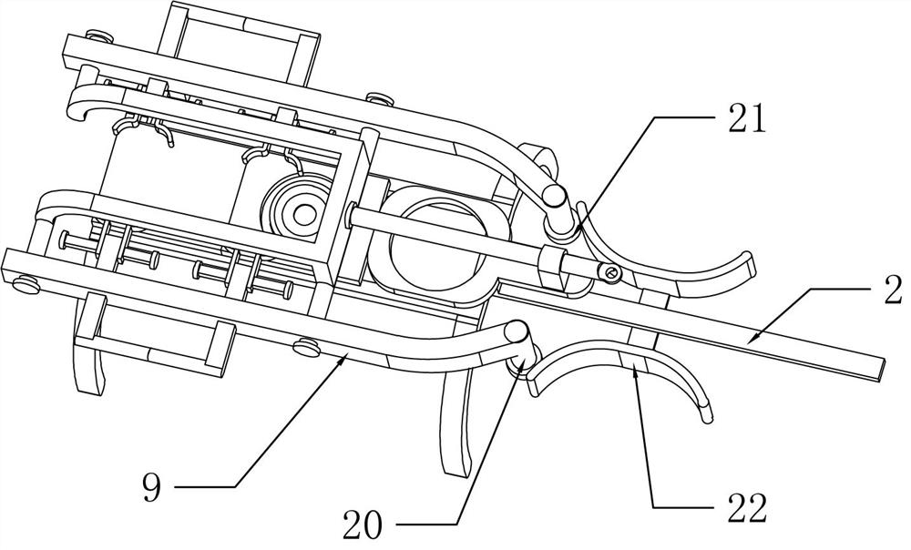
[0065] On the basis of Example 2, such as image 3 As shown, it also includes a rotating shaft 20, a pressure roller 21 and a pressure bearing track 22. A rotating shaft 20 is fixedly connected to the right end of the movable plate 9 on both sides, and a pressure roller 21 is connected to the lower ends of the two rotating shafts 20 for rotation. The pressure-bearing rails 22 are arranged symmetrically and fixedly connected to the middle parts of the front and rear sides of the support plate 2 respectively, and the pressure rollers 21 on both sides are in contact with the pressure-bearing rails 22 .
[0066] When the moving frame 8 moved to the right, the pressure rollers 21 below the movable plates 9 on both sides of the moving frame 8 moved along the bearing track 22. Get closer to the inside to realize the function of automatic clamping. When the movable frame 8 moves left and right, the movable plates 9 on both sides break away from the arc-shaped convex position of the pr...
PUM
 Abstract
Description
Claims
Application Information
 - R&D Engineer
- R&D Manager
- IP Professional
- Industry Leading Data Capabilities
- Powerful AI technology
- Patent DNA Extraction
Browse by: Latest US Patents, China's latest patents, Technical Efficacy Thesaurus, Application Domain, Technology Topic, Popular Technical Reports.
© 2024 PatSnap. All rights reserved.Legal|Privacy policy|Modern Slavery Act Transparency Statement|Sitemap|About US| Contact US: help@patsnap.com


