Characteristic pollutant environment monitoring system

An environmental monitoring system and a technology of characteristic pollutants, applied in the direction of measuring devices, analyzing gas mixtures, instruments, etc., can solve the problems of low level of informatization, weak construction of basic testing equipment, and the quality of monitoring data needs to be improved, so as to achieve extended work The effect of duration

Pending Publication Date: 2020-10-02
北京康尔兴科技发展有限公司
View PDF0 Cites 0 Cited by
  • Summary
  • Abstract
  • Description
  • Claims
  • Application Information

AI Technical Summary

Problems solved by technology

[0003] At present, more and more attention is paid to environmental monitoring, but the construction of many basic testing equipment is still very weak. It is difficult to provide accurate monitoring data through manual supervision and video grid monitoring. The next step is to make a breakthrough in refinement
Traditional air quality monitoring automatic stations are composed of large-scale equipment, and need to build a station building for installation. At the same time, a large amount of maintenance costs have to be spent every year. Due to the emergence of these situations, the establishment of automatic monitoring stations is limited. Yes, lack of a complete large-scale gas monitoring system
[0004] Many places in China have made beneficial attempts to monitor atmospheric grids, but there are still problems such as incomplete coverage and monitoring elements, low level of informatization, poor integration of monitoring and supervision, and the quality of monitoring data needs to be improved. It is difficult to meet the needs of air pollution control. need

Method used


Image

  • Characteristic pollutant environment monitoring system
  • Characteristic pollutant environment monitoring system
  • Characteristic pollutant environment monitoring system

Examples


Embodiment Construction

[0058] The following will clearly and completely describe the technical solutions in the embodiments of the present invention with reference to the accompanying drawings in the embodiments of the present invention. Obviously, the described embodiments are only some of the embodiments of the present invention, not all of them. Based on the embodiments of the present invention, all other embodiments obtained by persons of ordinary skill in the art without creative efforts fall within the protection scope of the present invention.

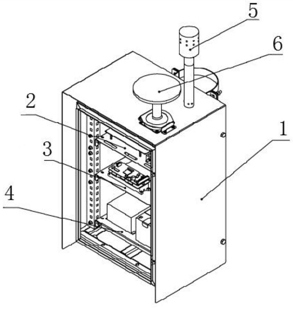
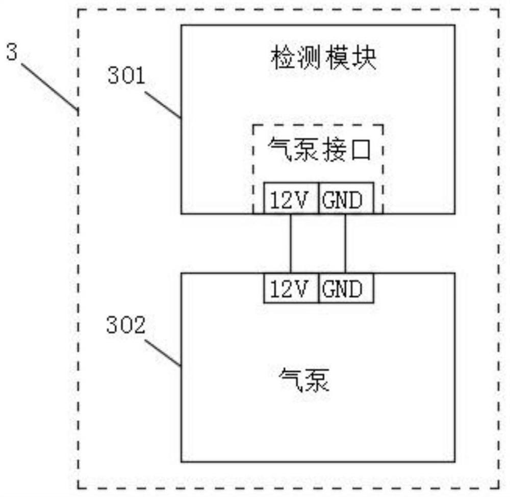
[0059] see Figure 1-4 As shown, this embodiment is a characteristic pollutant environment monitoring system, including a housing 1, a control unit 2, a detection unit 3, a power supply unit 4, a pre-processing unit 5 and a server 7, and the inner cavity of the housing 1 adopts A three-layer installation structure, and the three-layer installation structure is provided with a control unit 2, a detection unit 3 and a power supply unit 4 in sequence fro...


PUM


Abstract

The invention discloses a characteristic pollutant environment monitoring system. The system comprises a shell, a control unit, a detection unit, a power supply unit, a pretreatment unit and an antenna; an inner cavity of the shell is of a three-layer installation structure; the control unit, the detection unit and the power supply unit are sequentially arranged on the three-layer mounting structure from top to bottom; the pretreatment unit and the antenna are arranged at the top of the shell; the pretreatment unit is communicated with the air inlet of the shell; the shell is a stainless steelshell, so a power-off / power-on alarm function is realized; when the equipment is powered off in the running process, the state of the equipment can be remotely judged, a low-power-consumption mode after power failure is achieved, the working time of the equipment is prolonged, an independent instruction set remote control function is achieved, maintenance and detachment are achieved, internal parts of the equipment exist in a modular mode, maintenance is convenient, and maintenance cost is reduced conveniently.

Description

technical field [0001] The invention relates to the technical field of factory boundary environment monitoring, in particular to a characteristic pollutant environment monitoring system. Background technique [0002] While the local economy is developing rapidly, environmental pollution incidents such as water, air and noise continue to appear in different degrees in various regions, seriously affecting people's quality of life and hindering the sustainable development of the local economy. Many regions in my country are facing tremendous pressure to improve the quality of the atmospheric environment. With the promulgation and implementation of various environmental protection policies and regulations formulated by the state, local governments at all levels are paying more and more attention to environmental governance within the direct-controlled areas, and have increased environmental monitoring. According to the investment intensity, various regions have successively plann...

Claims


Application Information

Patent Timeline
IPC IPC(8): G01N33/00
CPCG01N33/0009G01N33/0073
Inventor 蔡兰宇赵天悦任士坡
Owner 北京康尔兴科技发展有限公司
Why Eureka
Try Eureka