
Hydraulic self-driven drag reduction slime diluting and releasing device

A release device and self-driven technology, which is applied to mixers with rotating stirring devices, transportation and packaging, mixers, etc., can solve the problems of not being suitable for carrying drag-reducing mucus, difficulty in releasing drag-reducing mucus, and large bending range. Large engineering application value, good dilution ability, and the effect of reducing mechanical noise

Active Publication Date: 2020-10-02
NORTHWESTERN POLYTECHNICAL UNIV
View PDF11 Cites 2 Cited by
  • Summary
  • Abstract
  • Description
  • Claims
  • Application Information

AI Technical Summary

Problems solved by technology

In the invention patent CN201910168276.3 "A Mucus Drag Reduction Device for Underwater Vehicles", the drag reduction device includes a liquid storage tank and a shunt pipe. By designing a drag reduction mucus injection device, the consumption of its drag reduction mucus is reduced. Drag-reducing mucus can only play a drag-reducing role at low concentrations. Due to the limited power consumption and space of the aircraft, it is not suitable to carry too much drag-reducing mucus
In the invention patent CN201811053561.2 "A Rapid and Uniform Dilution Device for Thick Polymer Mucus", the dilution device includes a storage room, a mixing section, and a pipe bend section, which can enable the aircraft to carry a small amount of high-concentration drag-reducing mucus. Low-concentration drag-reducing mucus is obtained by diluting in the mixing section and blending in the elbow section. However, the blending in the elbow section brings about a large loss along the way, and on the other hand, the large bending range makes it difficult to release the drag-reducing mucus. Even clogging due to prolonged release of mucus

Method used


Image

  • Hydraulic self-driven drag reduction slime diluting and releasing device
  • Hydraulic self-driven drag reduction slime diluting and releasing device
  • Hydraulic self-driven drag reduction slime diluting and releasing device

Examples


Embodiment Construction

[0022] This embodiment is a hydraulic self-driven drag-reducing mucus dilution release device.

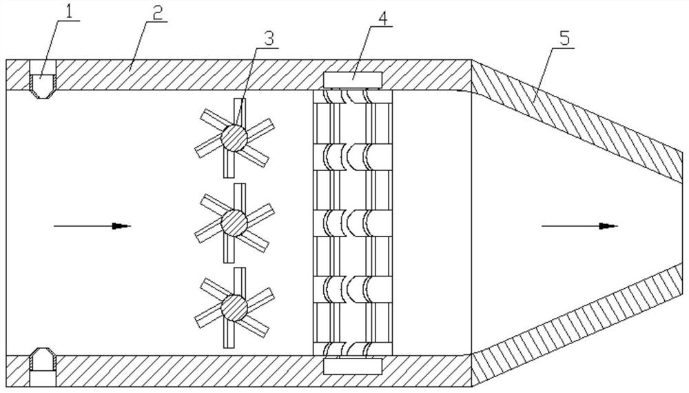
[0023] refer to Figure 1 ~ Figure 3 , figure 1 The middle arrow is the direction of water flow; figure 2 The arrows in the middle horizontal direction are the direction of water flow, and the arrows in the vertical direction are the direction of mucus flow.

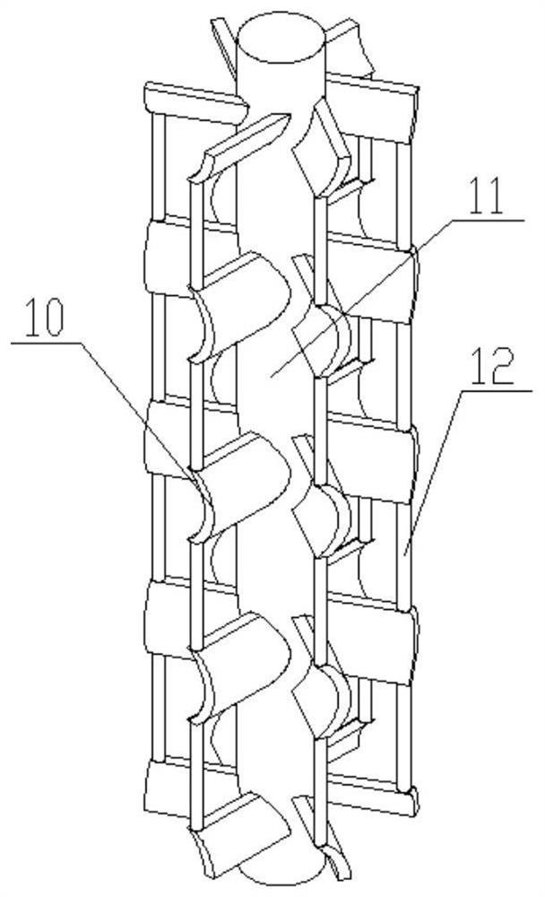
[0024] In this embodiment, the hydraulic self-driven drag-reducing mucus dilution release device consists of a mucus nozzle 1, a dilution and mixing chamber 2, a stirring rod 3, a release nozzle 5, a water inlet pipe 6, an electromagnetic flowmeter 7, a mucus delivery pipeline 8, and a mucus dilution Release device 9, hydraulic turbine 10, support rod 11, stirring round rod 12; electromagnetic flowmeter 7 is installed on water inlet pipe 6, and dilution and mixing chamber 2 is located at the rear of water inlet pipe 6. Wherein, the dilution and blending chamber is a hollow cuboid with open ends, the rear of the dilution a...


PUM


Abstract

The invention discloses a hydraulic self-driven anti-drag slime diluting and releasing device which is composed of a slime nozzle, a diluting and mixing cavity, a stirring rod and a releasing nozzle.The electromagnetic flowmeter is mounted on the water inlet pipe; the dilution mixing cavity is positioned at the rear part of the water inlet pipe; the diluting and mixing cavity and the release nozzle are connected into an integrated structure; the release nozzle is of a reducing section, wherein the stirring rod is located in the diluting and mixing cavity and connected to the diluting and mixing cavity through a bearing, the slime nozzle is fixed in a through hole in the front portion of the diluting and mixing cavity and is in interference fit with the through hole, and the slime nozzle is used for spraying resistance-reducing thick slime to be mixed and diluted with inflow water. The diluting and mixing cavity is self-driven by inflow water force to realize uniform mixing, the designof the stirring rod prevents the macromolecular chain of the drag reduction slime from being broken during stirring and mixing, and the drag reduction effect is lasting and effective. The anti-drag slime diluting and releasing device can realize dilution, blending and spraying of the anti-drag slime by sharing one diluting and blending cavity, is simple in structure and has relatively high engineering application value.

Description

technical field [0001] The invention relates to drag reduction and acceleration technology for underwater vehicles, in particular to a hydraulic self-driven drag reduction mucus dilution release device. Background technique [0002] The speed of ships and underwater vehicles is an important indicator to measure their performance. Under the same input power, the speed is closely related to the size of the resistance. The resistance suffered by ships and underwater vehicles consists of three parts: frictional resistance, pressure difference resistance and wave-making resistance, of which frictional resistance accounts for the highest proportion. Reducing frictional resistance is the main method for increasing speed and reducing consumption. At present, mainstream drag reduction methods include super-hydrophobic drag reduction, groove drag reduction, micro-bubble drag reduction, and flexible wall drag reduction. It has reached a consensus that using polymers or surfactants as...

Claims


Application Information

Patent Timeline
IPC IPC(8): B01F5/04B01F5/02B01F7/00B01F7/04B01F3/08B01F3/10B01F23/47
CPCB01F23/483B01F23/471B01F23/47B01F23/43B01F25/27B01F25/31424B01F27/11B01F27/706B01F2101/48
Inventor 胡海豹孟凡哲郑珂史瑞琦郑美云杜鹏黄潇冯家兴张梦卓周嘉伟
Owner NORTHWESTERN POLYTECHNICAL UNIV
Learn More