A Resolver Software Decoding Method Applicable to Motor Control

A resolver and software decoding technology, applied in the field of resolvers, can solve the problems of requiring DSP chips and increasing the software load of the control processor, so as to achieve the effects of improving reliability, reducing system costs and improving accuracy

Active Publication Date: 2022-05-06
DELPHI TECH SUZHOU CO LTD
View PDF7 Cites 0 Cited by
  • Summary
  • Abstract
  • Description
  • Claims
  • Application Information

AI Technical Summary

Problems solved by technology

This approach increases the software load on the control processor and requires a DSP chip

Method used


Image

  • A Resolver Software Decoding Method Applicable to Motor Control
  • A Resolver Software Decoding Method Applicable to Motor Control

Examples


specific Embodiment

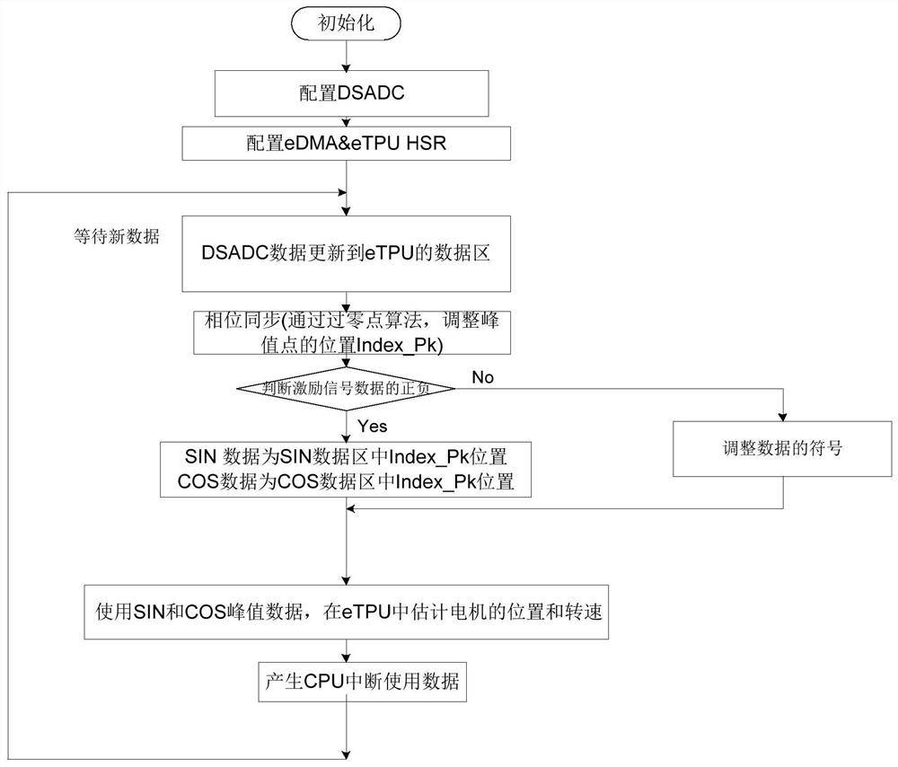
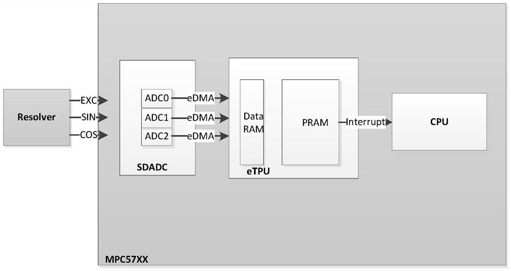
[0046](1) A resolver software decoding method, the method adopts the eTPU module of the MPC57xx series chip of NXP to realize resolver decoding. The eTPU (Enhanced Time Processor Uint) module is a programmable I / O controller with its own core and memory system that can perform complex timing and I / O management independently of the CPU. Firstly, sample the excitation signal and modulation signal by configuring the analog to digital converter ADC (analog to digital converter) module of the microcontroller; then configure the channel of the direct memory access module DMA() to transmit the sampled data and store it in the data RAM area of ​​the eTPU; Finally, the data is processed in the eTPU module, by using the peak value of the sampled data, and then the angle tracking observer estimates the position of the rotor, so as to realize the decoding function. The control includes the following steps:

[0047] a. Configure the ADC module and DMA module during CPU initialization. Acco...


PUM


Abstract

The invention relates to a software decoding method of a resolver suitable for motor control, the method comprising the following steps: Step 1: Initializing the CPU of the chip and configuring an ADC module to sample signals of the resolver; Step 2: DMA of the chip The channel is configured to store the resolver signal data sampled by the ADC module into the data RAM area in the eTPU module; step 3: perform data processing on the resolver signal data in the eTPU module to perform data processing on the resolver The position of the transformer rotor is estimated to enable decoding. Compared with the prior art, the present invention reduces the system cost and the space of the circuit board, improves the reliability of the circuit board, is independent of the CPU computing unit, thereby reducing the load rate of the chip, and reducing the time delay of the motor control application , Higher data synchronization, improved decoding accuracy at high speeds, etc.

Description

technical field [0001] The invention relates to the technical field of rotary transformers, in particular to a rotary transformer software decoding method suitable for motor control. Background technique [0002] A resolver is a sensor that measures the angle of rotation of a motor. Generally, a resolver consists of a stator and a rotor. For a variable reluctance resolver, the stator part contains three windings: one excitation winding and two two-phase windings. The primary winding of the transformer fixed on the stator is excited by a sinusoidal current, which induces a current in the rotor by electromagnetic induction. The two-phase windings are attached to the stator at the correct angle (90°), generating sine and cosine feedback currents. The relative magnitudes of the two phase voltages determine the angle of the rotor relative to the stator. [0003] The excitation signal of the resolver is a high-frequency sine signal, and the feedback sine and cosine signals are ...

Claims


Application Information

Patent Timeline
Patent Type & Authority Patents(China)
IPC IPC(8): H02P21/18H02P23/14G06F9/4401G06F13/28
CPCH02P21/18H02P23/14G06F9/4403G06F13/282
Inventor 马伟华王磊
Owner DELPHI TECH SUZHOU CO LTD
Why Eureka
Try Eureka