Novel swinging rotor compressor with low-pressure cavity in shell
A technology of rotor compressor and low-pressure cavity, applied in the field of compressors, can solve the problems of high temperature and low cooling capacity, and achieve the effects of not increasing the pressure, increasing the cooling capacity, and reducing noise and vibration
- Summary
- Abstract
- Description
- Claims
- Application Information
AI Technical Summary
Problems solved by technology
Method used
Image


Examples
Embodiment 1
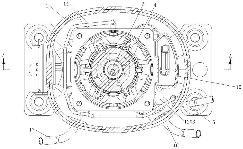
[0046] Such as Figure 1 to Figure 6 As shown, a new type of swinging rotor compressor with a low-pressure chamber in the casing includes a casing 1, and a pump body is installed inside the casing 1 through a number of elastic supports 2, and the pump body includes a cylinder assembly. A crankshaft 3 is sleeved on the cylinder assembly, and a motor 4 is sleeved above the crankshaft 3; the pump body also includes a swing rotor 8 arranged in the cylinder assembly, and the swing rotor 8 is set with the crankshaft connected; the swing rotor 8 passes through the slide 9 (see Figure 5 ) is connected with the cylinder assembly, and the swing rotor 8 and the sliding plate 9 divide the inner cavity of the cylinder assembly into a first compression chamber and a second compression chamber; the first compression chamber is passed through The air channel 10 is connected with a suction muffler chamber 12, the lower end of which is connected to the cylinder assembly through a direct inser...
Embodiment 2
[0062] This embodiment provides a specific structure of the suction muffler chamber in the first embodiment.
[0063] Such as Figure 7 and Figure 8 As shown, the suction muffler chamber 12 is divided into an upper muffler chamber 1202 and a lower muffler chamber 1201 by a transverse partition 21, and the transverse divider 21 is provided with a communication hole 2101; the lower muffler chamber 1201 is far away from the upper muffler chamber. One side of the muffler chamber 1202 is provided with an air suction and air outlet pipe 1204, the air inhalation air outlet pipe 1204 is set close to the outer edge of the lower muffler chamber 1201, and both sides of the air suction air outlet pipe 1204 are respectively provided with protruding mounting parts 1206, the installation part 1206 is provided with a number of installation holes 1207, the end of the suction outlet pipe 1204 is provided with a straight-in suction outlet 1205; the side of the upper muffler chamber 1202 is con...
Embodiment 3
[0071] This embodiment provides a specific structure of the exhaust cover assembly in the embodiment.
[0072] Such as Figure 9 and Figure 10 As shown, the exhaust cover assembly 13 includes a cylinder connection cover 1301 and an exhaust muffler cover 1302 connected as one; the interior of the exhaust muffler cover 1302 is separated into two exhaust chambers by a partition 1305, and the partition The plate 1305 is provided with an insertion tube 1306 to communicate with the adjacent exhaust chambers; the exhaust chamber on one side is connected with the exhaust connecting pipe 1304, and the exhaust chamber on the other side is connected to the exhaust chamber through the connecting pipe 1303. The cylinder is connected to the cover 1301 . The inner exhaust coil 14 is inserted into and connected to the exhaust connecting pipe 1304 .
[0073] Further, such as Figure 11 As shown, the cylinder connection cover 1301 has an inner cavity 1309, and the connecting pipe 1303 is c...
PUM
 Abstract
Description
Claims
Application Information
 - R&D
- Intellectual Property
- Life Sciences
- Materials
- Tech Scout
- Unparalleled Data Quality
- Higher Quality Content
- 60% Fewer Hallucinations
Browse by: Latest US Patents, China's latest patents, Technical Efficacy Thesaurus, Application Domain, Technology Topic, Popular Technical Reports.
© 2025 PatSnap. All rights reserved.Legal|Privacy policy|Modern Slavery Act Transparency Statement|Sitemap|About US| Contact US: help@patsnap.com