Touch display module, manufacturing method thereof and display device
A touch display and display module technology, which is applied in nonlinear optics, instruments, optics, etc., can solve the problems of image display cost waste, bubble generation, etc.
- Summary
- Abstract
- Description
- Claims
- Application Information
AI Technical Summary
Problems solved by technology
Method used
Image
Examples
Embodiment 1
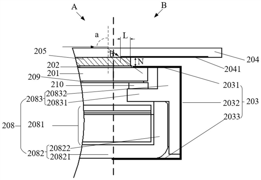
[0045] refer to figure 2 , shows a cross-sectional view of a touch display module according to an embodiment of the present invention.
[0046] The present invention provides a touch display module, including: a display module and a touch panel 204, and the display module includes a display panel 201, a first polarizer 202, and an adhesive component 203;
[0047] Wherein, the first adhesive portion 2031 of the adhesive member 203 and the first polarizer 202 are located on the light emitting side of the display panel 201, and the orthographic projection of the first adhesive portion 2031 of the adhesive member 203 on the display panel 201 is the same as that of the first polarizer 202. There is no overlapping area in the orthographic projection of a polarizer 202 on the display panel 201;
[0048] The touch panel 204 is fixedly connected to the first polarizer 202 in the display module through the first optical glue 205, and the orthographic projection of the first optical gl...
Embodiment 2
[0082] An embodiment of the present invention includes a display device, including the above-mentioned touch display module.
[0083] For the specific description of the touch display module, reference may be made to the description of Embodiment 1, which will not be repeated in this embodiment of the present invention.
[0084] The display device also includes devices such as a touch driver chip and a display driver chip.
[0085] In the embodiment of the present invention, the display device is a touch display device, and the display device may be any narrow-frame product or component with display and touch functions, such as a mobile phone, a tablet computer, a television, a notebook computer, and a vehicle display product.
[0086] In the embodiment of the present invention,
[0087] By forming the first optical glue on the first polarizer, the orthographic projection of the first optical glue on the first polarizer is located inside the area where the first polarizer is ...
Embodiment 3
[0089] refer to Figure 5 , which shows a flow chart of a manufacturing method of a touch display module according to an embodiment of the present invention, which may specifically include the following steps:
[0090] Step 510, providing a display module; the display module includes a display panel, a first polarizer and an adhesive component.
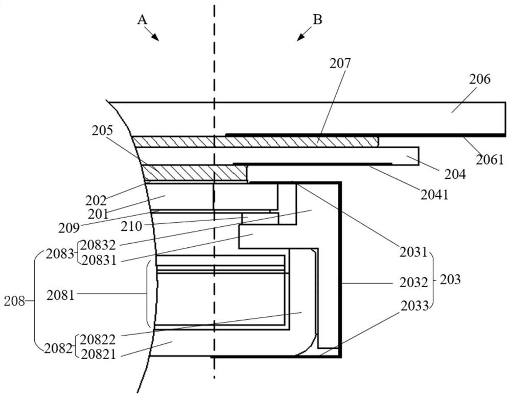
[0091] In an embodiment of the present invention, a display module is provided, the display module includes a display panel 201, a first polarizer 202 and an adhesive component 203, the display panel 201 includes a color filter substrate, an array substrate, and a display panel between the color filter substrate and the array substrate. In the liquid crystal layer between the substrates, the first polarizer 202 is located on the side of the color filter substrate in the display panel 201 away from the liquid crystal layer, wherein the first adhesive part 2031 of the glued part 203 and the first polarizer 202 are both located on the si...
PUM
| Property | Measurement | Unit |
|---|---|---|
| thickness | aaaaa | aaaaa |
| refractive index | aaaaa | aaaaa |
Abstract
Description
Claims
Application Information
 - R&D
- Intellectual Property
- Life Sciences
- Materials
- Tech Scout
- Unparalleled Data Quality
- Higher Quality Content
- 60% Fewer Hallucinations
Browse by: Latest US Patents, China's latest patents, Technical Efficacy Thesaurus, Application Domain, Technology Topic, Popular Technical Reports.
© 2025 PatSnap. All rights reserved.Legal|Privacy policy|Modern Slavery Act Transparency Statement|Sitemap|About US| Contact US: help@patsnap.com


