A vegetable stem cutting device
A technology of vegetable stems and cutting mechanism, which is applied in metal processing and other directions, can solve the problems of easily damaged hands, etc., and achieve the effects of easy collection, improved efficiency, and reduced manual operations
- Summary
- Abstract
- Description
- Claims
- Application Information
AI Technical Summary
Problems solved by technology
Method used
Image
Examples
Embodiment 1
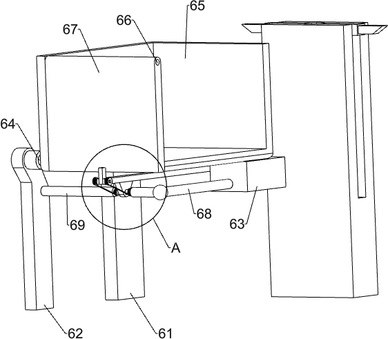
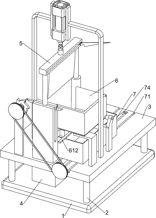
[0044] A device for cutting vegetable stems, such as figure 1 As shown, it includes a base 1, a support column 2, a base plate 3, a waste material frame 4, a cutting mechanism 5 and an unloading mechanism 6, a rectangular support column 2 is installed on the base 1, a base plate 3 is arranged on the top of the support column 2, and the base plate 3. There is a rectangular hole on the left side, a waste frame 4 is placed on the base 1 directly below the rectangular hole, a cutting mechanism 5 is installed on the front side of the bottom plate 3, and a material dumping mechanism 6 is arranged on the front side of the right part of the bottom plate 3.
[0045] When the vegetable stems are cut neatly, the vegetable stems are manually put into the parts of the unloading mechanism 6, the collection box is placed on the right front side of the base plate 3, and then the telescopic rods of the parts of the cutting mechanism 5 are manually controlled to elongate, and the cutting mechani...
Embodiment 2
[0047] Specifically, such as Figure 2-5As shown, the cutting mechanism 5 includes a square cylinder 51, a circular cylinder 53, a first elastic member 55, a piston rod 56, a connecting block 57, a cutter 58, an L-shaped pole 59 and a cylinder 510, and the left front side of the base plate 3 is equipped with Square tube 51, the inside of square tube 51 is provided with the first hole 52, and the middle part of bottom plate 3 left side is equipped with circular tube 53, and circular tube 53 inside offers the second hole 54, square tube 51 and circular tube 53 bottom walls Connected with a first elastic member 55, the end of the first elastic member 55 is provided with a piston rod 56, the piston rods 56 on both sides are respectively slidably located in the first hole 52 and the second hole 54, between the tops of the piston rods 56 on both sides Connecting block 57 is installed, and connecting block 57 bottoms are provided with cutter 58, and base plate 3 front portion left an...
Embodiment 3
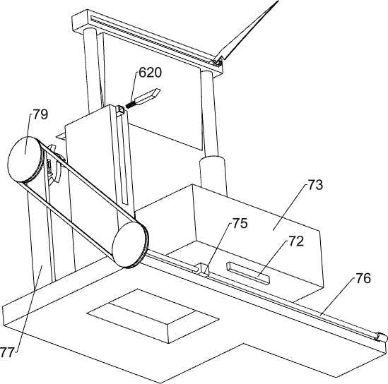
[0052] refer to Figure 5-6 As shown in the diagram, it also includes a collection mechanism 7, the collection mechanism 7 includes a first slide block 72, a collection frame 73, a nut 75, a screw mandrel 76, a second bearing seat 77, a drive shaft 78, a belt drive 79, a ratchet 710, hexagonal block 711, spring clip 712 and handle 713, the bottom plate 3 right side is provided with the first chute 71, the sliding type in the first chute 71 is provided with the first slide block 72, the first slide block 72 top Be connected with collecting frame 73, base plate 3 right side is provided with strip groove 74, and strip groove 74 is positioned at the left side of first chute 71, and the rotary type in strip groove 74 is provided with screw mandrel 76, and screw mandrel 76 front sides are equipped with Nut 75, nut 75 tops are connected with collecting frame 73 bottoms, base plate 3 left fronts are equipped with second bearing seat 77, and second bearing seat 77 tops are rotatably pr...
PUM
 Abstract
Description
Claims
Application Information
 - R&D
- Intellectual Property
- Life Sciences
- Materials
- Tech Scout
- Unparalleled Data Quality
- Higher Quality Content
- 60% Fewer Hallucinations
Browse by: Latest US Patents, China's latest patents, Technical Efficacy Thesaurus, Application Domain, Technology Topic, Popular Technical Reports.
© 2025 PatSnap. All rights reserved.Legal|Privacy policy|Modern Slavery Act Transparency Statement|Sitemap|About US| Contact US: help@patsnap.com


