
Laser cutting device with protective structure

A laser cutting and protective structure technology, applied in laser welding equipment, welding equipment, metal processing equipment, etc., can solve the problems of impurities entering, incomplete cutting of workpieces, affecting laser beam focusing, etc., to achieve stable cutting head and avoid impact Effect

Inactive Publication Date: 2020-09-18
东莞市奇趣机器人科技有限公司
View PDF0 Cites 2 Cited by
  • Summary
  • Abstract
  • Description
  • Claims
  • Application Information

AI Technical Summary

Problems solved by technology

[0004] The object of the present invention is to provide a kind of laser cutting equipment with protective structure, in order to solve the debris and melted metal produced by the existing laser cutting proposed in the above-mentioned background technology, for effective collection and treatment, impurities are easy to enter into the cutting The zoom mirror inside the head affects the zooming of the laser beam, resulting in abnormally high temperature of the cutting head and incomplete cutting of the workpiece

Method used


Image

  • Laser cutting device with protective structure
  • Laser cutting device with protective structure
  • Laser cutting device with protective structure

Examples


Embodiment Construction

[0027] The technical solutions in the embodiments of the present invention will be clearly and completely described below in conjunction with the accompanying drawings in the embodiments of the present invention. Obviously, the described embodiments are only some of the embodiments of the present invention, not all of them. Based on The embodiments of the present invention and all other embodiments obtained by persons of ordinary skill in the art without making creative efforts belong to the protection scope of the present invention.

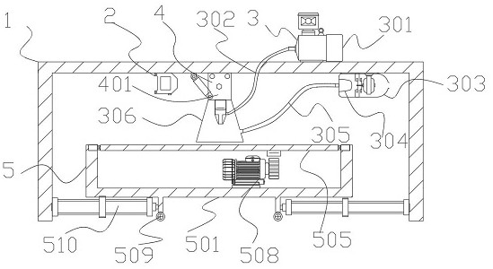
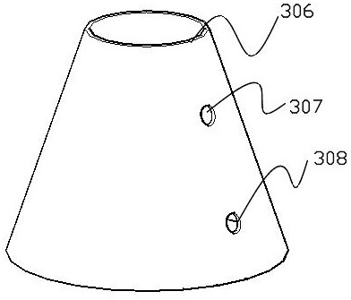
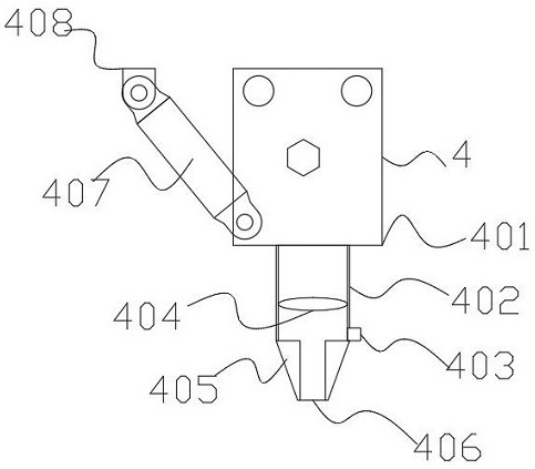
[0028] 1. See Figure 1-6 , the present invention provides a technical solution: a laser cutting device with a protective structure, including a frame 1, a convection module 3, a cutting module 4 and a station module 5, a displacement sensor 2 is installed on the inner top left side of the frame 1, and the convection A blower 301 is arranged above the side of the module 3, and the convection module 3 is located on the right side of the frame 1. ...


PUM


Abstract

The invention discloses a laser cutting device with a protective structure. The laser cutting device comprises a rack, a convection module, a cutting module and a station module. An air blower is arranged above the right side of the convection module, and the convection module is located at the right side of the rack. The convection module comprises the air blower, an air shower pipe, a dust removal fan, a dust collection chamber, an air suction pipe, a protective cover, an air inlet and an air suction inlet. The air blower is arranged above the right side of the rack. The air shower pipe is connected to the output end of the air blower. The dust removal fan is installed on the right side inside the rack. The air suction pipe is connected to the left side of the dust removal fan, and the left end of the air suction pipe is connected with the air suction inlet. A laser generator is arranged above the cutting module, and the cutting module is located at the top of the inner side of the rack. A base plate is installed in the middle of the station module, and the station module is located at the bottom of the inner side of the rack. According to the laser cutting device with the protective structure, a user can effectively protect device operators through the convection module.

Description

technical field [0001] The invention relates to the technical field of laser cutting, in particular to a laser cutting device with a protective structure. Background technique [0002] Laser cutting is to use a focusing mirror to focus the CO2 laser beam on the surface of the material to melt the material, and make the laser beam and the material move relative to each other along a certain trajectory, thereby forming a certain shape of the slit. Laser cutting technology is widely used in metal and non-metal materials During the processing, the processing time can be greatly reduced, the processing cost can be reduced, and the quality of the workpiece can be improved. However, the existing laser cutting equipment lacks effective protection means when cutting the plate, and the debris generated by laser cutting and the molten metal In order to carry out effective collection and processing, it is easy for impurities to enter the zoom mirror inside the cutting head, which affect...

Claims


Application Information

Patent Timeline
Patent Type & Authority Applications(China)
IPC IPC(8): B23K26/38B23K26/142B23K26/08B23K26/03B23K26/70
CPCB23K26/03B23K26/083B23K26/38B23K26/142B23K26/702B23K26/706
Inventor 邓凯胡常华范朝辉
Owner 东莞市奇趣机器人科技有限公司
Learn More