
A zigzag stripline common-mode filter circuit without vias

A common-mode filter and common-mode filter technology, which is applied in the direction of circuits, electrical components, waveguide devices, etc., can solve the problems of poor filtering effect, instability, and damage to the shielding effect of the differential line reference ground, so as to achieve increased electromagnetic coupling, The effect of suppressing the increase of depth and ensuring the filtering effect and stability

Active Publication Date: 2021-08-17
ZHEJIANG UNIV
View PDF11 Cites 0 Cited by
  • Summary
  • Abstract
  • Description
  • Claims
  • Application Information

AI Technical Summary

Problems solved by technology

[0006] In order to overcome the problem that the common mode filter structure in the prior art usually destroys the shielding effect of the differential line reference ground, resulting in poor or unstable filtering effect, the present invention provides a zigzag stripline common mode filter without vias Filtering circuit, the common mode filter is applied to the strip differential line, which is composed of two single-ended lines with coupling relationship and its upper and lower ground planes. This structure transmits differential signals with complementary (anti-phase) relationship, common mode The filter and the differential line are set on the same PCB wiring layer to prevent common-mode noise on the differential line, and the common-mode filter has no connection vias, and the processing technology is simple. While effectively filtering the common-mode noise, the differential-mode The signal influence is small, and the filtering effect is stable

Method used


Image

  • A zigzag stripline common-mode filter circuit without vias
  • A zigzag stripline common-mode filter circuit without vias
  • A zigzag stripline common-mode filter circuit without vias

Examples


Embodiment Construction

[0023] The present invention will be further described below in conjunction with the accompanying drawings.

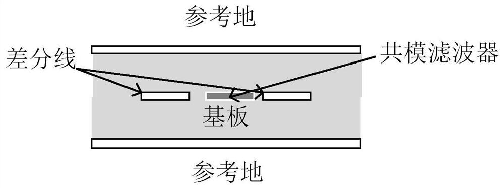
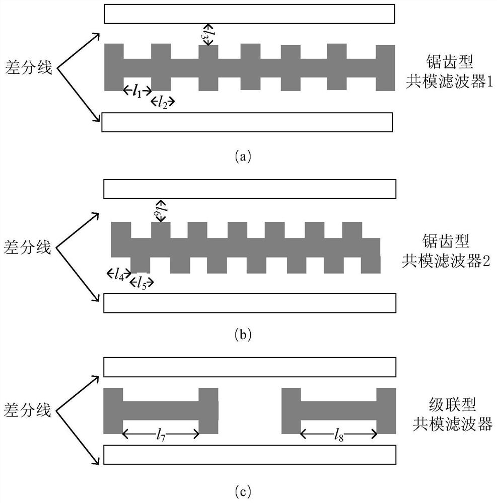
[0024] A zigzag stripline common-mode filter circuit without vias, including a dielectric substrate, a metal ground plane arranged above and below the dielectric substrate, a pair of differential lines and a common-mode filter arranged in the middle of the dielectric substrate, its cross section Respectively as figure 1 As shown, the differential line is a strip differential line, and the differential line is composed of two single-ended lines with a coupling relationship and their upper and lower ground planes. This structure transmits differential signals with a complementary (anti-phase) relationship. The common mode filter is a sheet metal structure located in the middle of the differential line, and the width of the common mode filter presents a zigzag concave-convex distribution along the arrangement direction of the differential line.

[0025] Common mode filte...


PUM


Abstract

The invention discloses a zigzag stripline common-mode filter circuit without via holes. This invention is used to suppress the common-mode conduction noise on the high-speed strip differential line. A zigzag line is added in the middle of the differential line as a common-mode filter. on the same floor. The common-mode current on the differential line is efficiently coupled to the common-mode filter through the concave-convex edge of the zigzag trace, and then the common-mode current on the differential line is blocked by the self-resonance of the common-mode filter. The invention overcomes the problem that the existing common mode filter cannot efficiently couple the common mode current on the strip differential line, thereby improving the width and depth of the stop band of the common mode filter. On the other hand, since the common-mode filter of the present invention does not require via holes and is on the same layer as the differential line, the influence of the common-mode filter on the wiring of the differential line is minimized, and it is very suitable for high-density wiring and common-mode filtering. to use space-constrained high-speed differential lines.

Description

technical field [0001] The invention relates to the technical field of common-mode noise suppression on differential lines in PCB boards, in particular to a zigzag stripline common-mode filter circuit without vias. Background technique [0002] As the signal rate continues to increase, differential lines have become a common transmission form for high-speed interconnection. Differential signals have significant advantages such as strong anti-interference ability, effective suppression of external electromagnetic interference, and accurate timing positioning. However, the differential line structure not only transmits differential signals that carry information, but also transmits common-mode noise that does not carry information but causes electromagnetic interference. The discontinuous structure on the PCB board, the unbalance of the differential pair, the crossing between layers, and the common mode signal output in the chip will all bring the risk of common mode noise. ...

Claims


Application Information

Patent Timeline
Patent Type & Authority Patents(China)
IPC IPC(8): H01P1/203H01P1/212
CPCH01P1/203H01P1/212
Inventor 魏兴昌宋天豪
Owner ZHEJIANG UNIV
Learn More