Eureka AIR delivers breakthrough ideas for toughest innovation challenges, trusted by R&D personnel around the world.

Automatic metal part welding device

A technology for automatic welding and metal parts, which is applied in the direction of auxiliary devices, welding equipment, welding equipment, etc., can solve the problems of welding work influence, small application range, and difficult fixation, etc., and achieve comprehensive welding, enhanced application range, and improved accuracy. Effect

Inactive Publication Date: 2020-09-11
厉佳璇
View PDF0 Cites 1 Cited by
  • Summary
  • Abstract
  • Description
  • Claims
  • Application Information

AI Technical Summary

Problems solved by technology

[0003] Existing welding devices can only fix metal parts of a specific shape, resulting in a small scope of application and increased costs. Moreover, when the device is welding a tubular object, it is difficult to fix it because the surface of the tubular object is relatively smooth, and it is easy to fix it. Therefore, in view of the above status quo, it is urgent to develop an automatic welding device for metal parts to overcome the deficiencies in current practical applications.

Method used


Image

  • Automatic metal part welding device
  • Automatic metal part welding device
  • Automatic metal part welding device

Examples


Embodiment 1

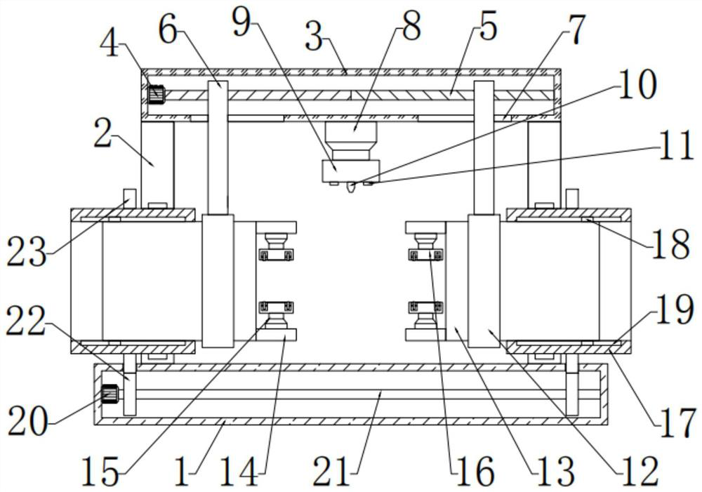
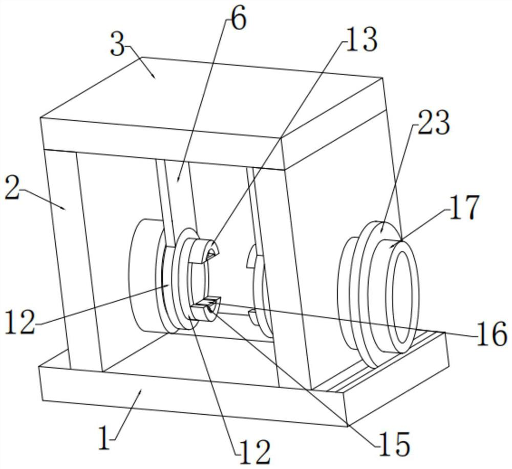
[0024] see Figure 1-3 , in an embodiment of the present invention, an automatic welding device for metal parts, including a base plate 1, the top of the left and right ends of the base plate 1 are fixedly connected with support plates 2, and the support plates 2 on both sides are provided with metal A clamping mechanism for parts, the top of the support plate 2 is fixedly connected with a top plate 3, the bottom of the top plate 3 is provided with a welding mechanism, and the left and right sides of the welding mechanism are provided with adjustment mechanisms connected with the clamping mechanism.

Embodiment 2

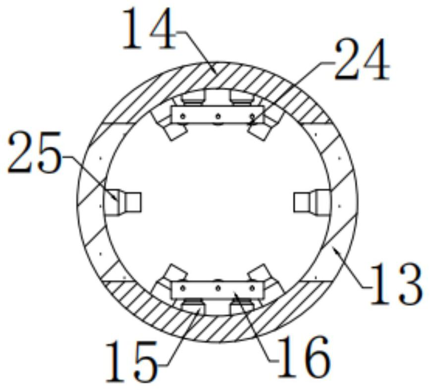
[0026] In this embodiment, the clamping mechanism includes a rotating cylinder 17 arranged on the supporting plate 2 in bearing connection, a fixed tube 13 is arranged inside the rotating cylinder 17, and the upper and lower sides of the fixed tube 13 are fixedly connected and set with limited positions. Block 18, the limit block 18 is slidingly connected with the limit groove 19 arranged on the inner side of the drum 17, and a plurality of third telescopic rods 25 are fixedly connected on the inner side wall of the fixed tube 13, and the fixed tube 13 is close to The upper and lower ends of one side of the welding mechanism are fixedly connected with a baffle plate 14, and the opposite side of the baffle plate 14 on both sides is fixedly connected with a second telescopic rod 15, and the other end of the second telescopic rod 15 is fixedly connected with a Clamping plate 16, by setting clamping mechanism, utilizes clamping plate 16, can provide fixing to plate or irregular met...


PUM


Abstract

The invention relates to the technical field of automatic equipment, in particular to an automatic metal part welding device. The automatic metal part welding device comprises a bottom plate, supporting plates are fixedly connected to the tops of the left end and the right end of the bottom plate, clamping mechanisms used for fixing metal parts are arranged on the supporting plates on the two sides, a top plate is fixedly connected to the tops of the supporting plates, a welding mechanism is arranged at the bottom of the top plate, and adjusting mechanisms connected with the clamping mechanisms are arranged on the left side and the right side of the welding mechanism. By arranging the clamping mechanisms and utilizing clamping plates, a plate or an irregular metal part can be fixed, a pipecan be fixed through third telescopic rods arranged on the inner side of a fixing pipe, and therefore, the device can be used for fixing metal parts with different shapes; and by arranging the adjusting mechanisms, the distance between the clamping mechanisms on the two sides can be changed, and the device can weld metal parts of different sizes.

Description

technical field [0001] The invention relates to the technical field of automation equipment, in particular to an automatic welding device for metal parts. Background technique [0002] The history of joining metals goes back thousands of years, with early soldering techniques seen in Bronze Age and Iron Age Europe and the Middle East. Thousands of years ago, the Babylonian Two Rivers Civilization began to use soldering technology. In 340 BC, welding technology was used in the manufacture of the 5.4-ton iron pillar of ancient Indian Delhi. Welding is a process in which two or more materials of the same or different materials are connected into one through bonding and diffusion between atoms or molecules. Welded products are lighter than riveted parts, castings and forgings, which can reduce the weight and save energy for transportation vehicles. The sealing performance of welding is good, and it is suitable for manufacturing various containers. [0003] Existing welding d...

Claims


Application Information

Patent Timeline
Patent Type & Authority Applications(China)
IPC IPC(8): B23K37/053B23K37/04B23K37/047B23K37/00B23K31/02
CPCB23K31/02B23K37/00B23K37/04B23K37/047B23K37/053
Inventor 厉佳璇
Owner 厉佳璇
Why Eureka
Eureka Blog
Learn More