
Die-casting part cutting device

A cutting device, die-casting technology, applied in the direction of positioning devices, maintenance and safety accessories, metal processing machinery parts, etc., can solve the problems of low work efficiency, debris splashing, accidental injury to others, etc., to achieve high practicability and improve work efficiency Effect

Inactive Publication Date: 2020-09-11
WUHU SUNVOUR DIE CASTING
View PDF6 Cites 5 Cited by
  • Summary
  • Abstract
  • Description
  • Claims
  • Application Information

AI Technical Summary

Problems solved by technology

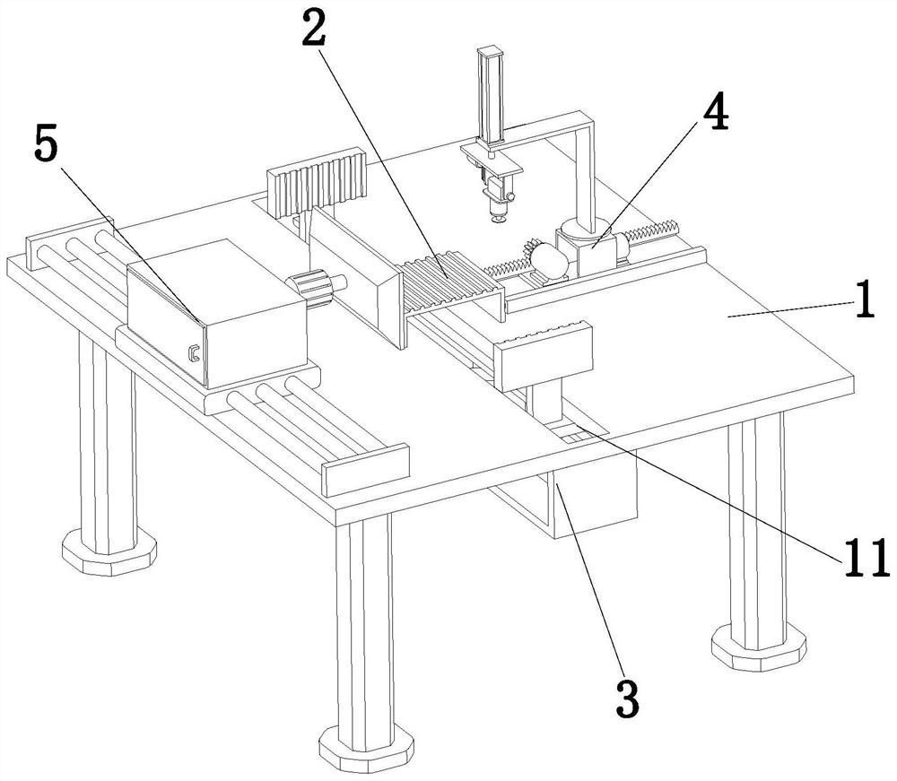
Die castings have different names in different places, such as die casting parts, pressure castings, die castings, die casting aluminum, die casting zinc parts, die casting copper parts, copper die castings, zinc die castings, aluminum die castings aluminum die castings, aluminum die castings Alloy castings, aluminum alloy die-casting parts, etc. At present, the blisters of die-castings are a major problem that plagues the die-casting industry. For the blisters that have appeared through subsequent machining of die-castings that have been produced, they are often compensated by repair welding; Cutting and reprocessing are required after welding. Existing die-casting cutting operations are generally done manually, with low work efficiency, and die-castings will generate a lot of debris during the cutting process, which is not convenient for cleaning and will accidentally hurt others

Method used


Image

  • Die-casting part cutting device
  • Die-casting part cutting device
  • Die-casting part cutting device

Examples


Embodiment Construction

[0023] In order to make the object, technical solution and advantages of the present invention clearer, the present invention will be further described in detail below in conjunction with the accompanying drawings and embodiments. It should be understood that the specific embodiments described here are only used to explain the present invention, not to limit the present invention.

[0024] The components of the embodiments of the invention generally described and shown in the figures herein may be arranged and designed in a variety of different configurations. Accordingly, the following detailed description of the embodiments of the invention provided in the accompanying drawings is not intended to limit the scope of the claimed invention, but merely represents selected embodiments of the invention.

[0025] Based on the embodiments of the present invention, all other embodiments obtained by persons of ordinary skill in the art without making creative efforts belong to the pro...


PUM


Abstract

The invention discloses a die-casting part cutting device and relates to the technical field of metal machining. The die-casting part cutting device comprises a cutting table, a carrying platform, a clamping mechanism, a cutting mechanism and a scrap removing mechanism. The middle position of the cutting table is provided with a fixing slot. The carrying platform is fixedly arranged in the middleposition of the cutting table. The clamping mechanism is fixedly arranged on the lower portion of the fixing slot of the cutting table. The cutting mechanism is fixedly arranged on one side of the upper surface of the cutting table. The working end of the cutting mechanism is located on the carrying platform. The scrap removing mechanism is located on the other side of the cutting table. The working end of the scrap removing mechanism is aligned with the carrying platform. The die-casting part cutting device completes automatic cutting operation of die-casting parts and scrap removing operation in the cutting process through cooperation of all the mechanisms on the cutting table and has high practicality.

Description

technical field [0001] The invention relates to the technical field of bearing detection, in particular to a cutting device for die castings. Background technique [0002] Die-casting is a kind of pressure-casting part. It uses a pressure-casting mechanical die-casting machine equipped with a casting mold to pour liquid copper, zinc, aluminum or aluminum alloy into the feed port of the die-casting machine, and passes through the die-casting machine. Die casting, casting copper, zinc, aluminum parts or aluminum alloy parts of the shape and size limited by the mold, such parts are usually called die castings. Die-casting parts have different names in different places, such as die-casting parts, pressure castings, die-casting parts, die-casting aluminum, die-casting zinc parts, die-casting copper parts, copper die-casting parts, zinc die-casting parts, aluminum die-casting parts aluminum die-casting parts, aluminum die-casting parts Alloy castings, aluminum alloy die-casting p...

Claims


Application Information

Patent Timeline
Patent Type & Authority Applications(China)
IPC IPC(8): B23D79/00B23Q3/06B23Q11/00
CPCB23D79/00B23Q3/062B23Q11/00B23Q11/0046
Inventor 肖明海修磊
Owner WUHU SUNVOUR DIE CASTING
Learn More