
Array substrate, display panel and display device

A technology for array substrates and base substrates, which is applied in the field of display panels, display devices, and array substrates, and can solve problems such as affecting display effects and delaying transmission of gate drive signals.

Active Publication Date: 2020-09-08
XIAMEN TIANMA MICRO ELECTRONICS
View PDF5 Cites 1 Cited by
  • Summary
  • Abstract
  • Description
  • Claims
  • Application Information

AI Technical Summary

Problems solved by technology

[0005] Embodiments of the present invention provide an array substrate, a display panel, and a display device, so as to solve the problems caused by the delay in the transmission of the gate drive signal caused by the gate drive signal transmission delay in the prior art due to the charge stored in the gate-drain parasitic capacitance during the transmission process of the gate drive signal. Display technical issues

Method used

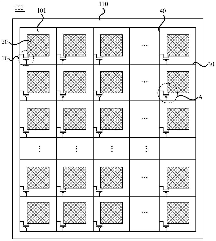
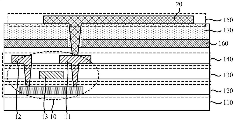

Image

  • Array substrate, display panel and display device
  • Array substrate, display panel and display device
  • Array substrate, display panel and display device

Examples


Embodiment Construction

[0036] The present invention will be further described in detail below in conjunction with the accompanying drawings and embodiments. It should be understood that the specific embodiments described here are only used to explain the present invention, but not to limit the present invention. In addition, it should be noted that, for the convenience of description, only some structures related to the present invention are shown in the drawings but not all structures.

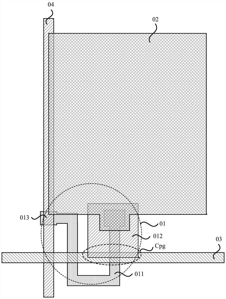
[0037] figure 1 It is a partial top view structure schematic diagram of the array substrate in the prior art. Such as figure 1 As shown, the array substrate includes thin film transistors 01 , pixel electrodes 02 , gate lines 03 and data lines 04 . Wherein, the thin film transistor 01 includes an active layer 011, a first electrode 012 and a second electrode 013, and the overlapping part of the gate line 03 and the active layer 011 is the gate of the thin film transistor 01; the first electrode 012 of the thin f...


PUM


Abstract

The embodiment of the invention provides an array substrate, a display panel and a display device. The array substrate comprises a substrate base plate, a semiconductor layer, a grid metal layer, a source-drain metal layer and a pixel electrode layer. An active layer of a thin film transistor is arranged on the semiconductor layer, a first electrode and a second electrode of the thin film transistor are arranged on the source-drain metal layer, a grid line is arranged on the grid metal layer, and the grid line is overlapped with a channel region of the active layer of the thin film transistor;the first electrode of the thin film transistor is electrically connected to the pixel electrode, wherein the orthographic projection of the first electrode on the substrate base plate is a special-shaped pattern, and the orthographic projection of the first electrode on the substrate base plate and the orthographic projection of the grid line on the substrate base plate are not overlapped with each other. According to the embodiment of the invention, the delay of a grid drive signal transmitted on the grid line can be reduced, thereby facilitating the improvement of the display uniformity.

Description

technical field [0001] The present invention relates to the field of display technology, in particular to an array substrate, a display panel and a display device. Background technique [0002] With the development of display technology, display panels with advanced functions have gradually become an important feature of today's consumer electronics products, among which liquid crystal display panels have gradually become an important feature of various electronic devices such as mobile phones, personal digital assistants (PDAs), digital cameras, computer screens Or a display panel with a high-resolution color screen widely used in notebook computer screens. [0003] Currently, a liquid crystal display panel driven by a thin film transistor (Thin Film Transistor, TFT) is the most common liquid crystal display panel, and the TFT array substrate of the liquid crystal display panel is usually provided with TFTs, gate lines, data lines, and pixel electrodes. The gate of the TFT...

Claims


Application Information

Patent Timeline
Patent Type & Authority Applications(China)
IPC IPC(8): H01L27/12H01L29/417H01L29/423G02F1/1362
CPCH01L27/124H01L29/42384H01L29/42356H01L29/41733G02F1/136286
Inventor 姚华鑫吴薇吴昊沈柏平
Owner XIAMEN TIANMA MICRO ELECTRONICS
Learn More