
Direct-current support film capacitor resistant to large ripple current

A film capacitor and DC support technology, applied in the direction of film/thick film capacitors, capacitors, laminated capacitors, etc., can solve the problems of insufficient ripple current capability and easy internal heating, etc., to increase ripple current capability and reduce Equivalent series resistance ESR, effect of reducing thermal resistance

Pending Publication Date: 2020-09-08
SHENZHEN HOVERBIRD ELECTRONICS TECH CO LTD
View PDF0 Cites 4 Cited by
  • Summary
  • Abstract
  • Description
  • Claims
  • Application Information

AI Technical Summary

Problems solved by technology

[0003] The technical problem to be solved by the present invention is to provide a DC supporting film capacitor capable of withstanding large ripple current, which aims to solve the problem that the traditional capacitor structure in the prior art cannot withstand ripple current and is easily affected by high-frequency ripple current. There are technical problems with internal heating and many defects

Method used


Image

  • Direct-current support film capacitor resistant to large ripple current
  • Direct-current support film capacitor resistant to large ripple current
  • Direct-current support film capacitor resistant to large ripple current

Examples


Embodiment

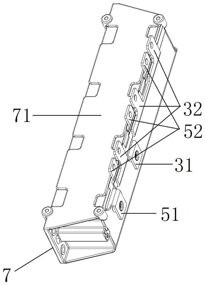
[0030] Shown in conjunction with the accompanying drawings is a specific embodiment of a DC support film capacitor with high ripple current resistance according to the present invention, which mainly includes a capacitor body 1, and the capacitor body 1 includes a core group 2, a lower busbar 3, an insulating layer 4, Upper busbar 5.

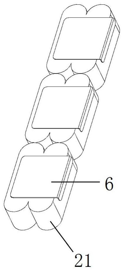
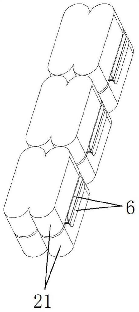
[0031] The core set 2 includes twelve cores 21 , each core 21 is formed by winding a metallized polypropylene film 22 , and the ratio of length to width of the metallized polypropylene film 22 is 3-9:1. The metallized polypropylene film 22 has a metal conductive region 22a, the metal conductive region 22a is provided with a T-type insulating region 22b, and the T-type insulating region 22b has several, distributed along the length direction of the metallized polypropylene film 22 at equal intervals so that The metal conductive region 22a is divided into several regions, and a fuse 22c is provided between two adjacent T-shaped insulating regions ...


PUM


Abstract

The invention discloses a direct-current supporting thin-film capacitor resistant to large ripple currents. The direct-current supporting thin-film capacitor comprises a capacitor body, which comprises a core group, upper and lower busbars and an insulating layer, wherein the core group comprises cores, the core is formed by winding a metallized polypropylene film, the film has a metal conductivearea, a plurality of T-shaped insulating areas are arranged on the metal conductive area, fuses are arranged between adjacent T-shaped insulating areas, the cores are arranged into two layers up and down, the lower busbar is arranged on one side of the core group and connected with the cores through welding copper plates, the upper busbar is of a [-shaped structure, the core group and the lower busbar are installed in the upper busbar, the cores are connected with the upper busbar, the insulating layer is arranged between the upper and lower busbars, the capacitor further comprises a shell made of a heat dissipation material, the capacitor body is installed in the shell and encapsulated through an epoxy resin, the upper busbar and the lower busbar are provided with connecting terminals located outside the shell, and the shell is provided with a heat dissipation face. According to the invention, the ripple current resistance can be improved, the equivalent series resistance and thermalresistance are reduced, and sufficient heat dissipation is realized.

Description

technical field [0001] The invention relates to a DC supporting film capacitor capable of withstanding large ripple current. Background technique [0002] The electric energy of the electric vehicle battery is generally transmitted to the inverter through a DC link circuit, and the inverter is converted into an AC power supply for the vehicle. This power supply method is called "DC-Link". In the DC link circuit It is necessary to connect a large-capacity DC support capacitor to provide support for the inverter circuit and filter out the ripple current generated by the inverter circuit. However, existing capacitors are not capable of withstanding ripple currents, and are prone to internal heating due to the influence of high-frequency ripple currents, and there are still many defects. Contents of the invention [0003] The technical problem to be solved by the present invention is to provide a DC supporting film capacitor capable of withstanding large ripple current, which...

Claims


Application Information

Patent Timeline
Patent Type & Authority Applications(China)
IPC IPC(8): H01G4/38H01G4/33H01G4/32H01G4/14H01G4/005H01G4/228H01G4/224H01G4/40H01G2/08
CPCH01G4/38H01G4/33H01G4/32H01G4/14H01G4/005H01G4/228H01G4/224H01G4/40H01G2/08
Inventor 李贵生刘斌杜野王会杨友凯
Owner SHENZHEN HOVERBIRD ELECTRONICS TECH CO LTD
Learn More