
Tail gas purification system and method for recycling smoke waste heat

A technology for exhaust gas purification and flue gas waste heat, which is applied in chemical instruments and methods, separation methods, gas treatment, etc., can solve the difficulty of increasing waste heat recovery from exhaust emissions, effective recovery and utilization technology is blank, and the operating temperature of wet desulfurization devices is low To achieve the effect of ensuring the uniformity of the airflow, optimizing the smoke flow field, and reducing energy consumption

Pending Publication Date: 2020-09-08
杭州蕴泽环境科技有限公司 +1
View PDF5 Cites 2 Cited by
  • Summary
  • Abstract
  • Description
  • Claims
  • Application Information

AI Technical Summary

Problems solved by technology

[0005] There are the following problems in the recovery of waste heat from power station and boiler tail gas: 1. The water vapor and SO in the flue gas X The gas is easy to cause acid dew point corrosion, and it is difficult to recover waste heat below the acid dew point temperature of flue gas; 2. The operating temperature of wet desulfurization device is low, which further increases the difficulty of waste heat recovery from exhaust emissions; 3. A large amount of waste heat of flue gas enters wet desulfurization The device evaporates water, and the residual heat of the flue gas causes a large water consumption in the operation of the wet desulfurization device
At present, the technology for effective recovery and utilization of waste heat below the acid dew point temperature of exhaust gas from power plants and boilers is still blank

Method used


Image

  • Tail gas purification system and method for recycling smoke waste heat
  • Tail gas purification system and method for recycling smoke waste heat
  • Tail gas purification system and method for recycling smoke waste heat

Examples


Embodiment Construction

[0049] The following will clearly and completely describe the technical solutions in the embodiments of the application with reference to the drawings in the embodiments of the application. Apparently, the described embodiments are only some of the embodiments of the application, not all of them. Based on the embodiments in this application, all other embodiments obtained by persons of ordinary skill in the art without making creative efforts belong to the scope of protection of this application.

[0050] In order to better describe and illustrate the embodiments of the application, reference may be made to one or more drawings, but additional details or examples used to describe the drawings should not be regarded as an invention of the application, the presently described implementation limitations on the scope of any of the examples or preferred modes.

[0051] It should be noted that when a component is said to be "connected" to another component, it may be directly connec...


PUM

PropertyMeasurementUnit
Tube wall thicknessaaaaaaaaaa
Diameteraaaaaaaaaa
Apertureaaaaaaaaaa

Abstract

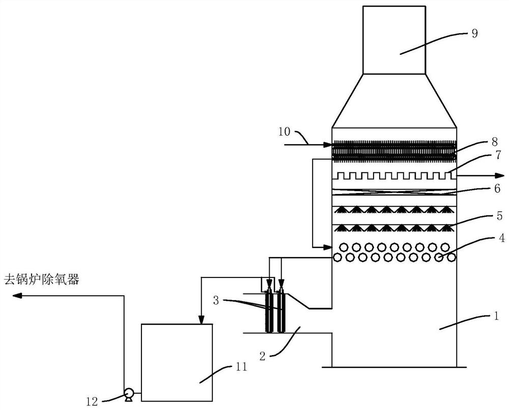
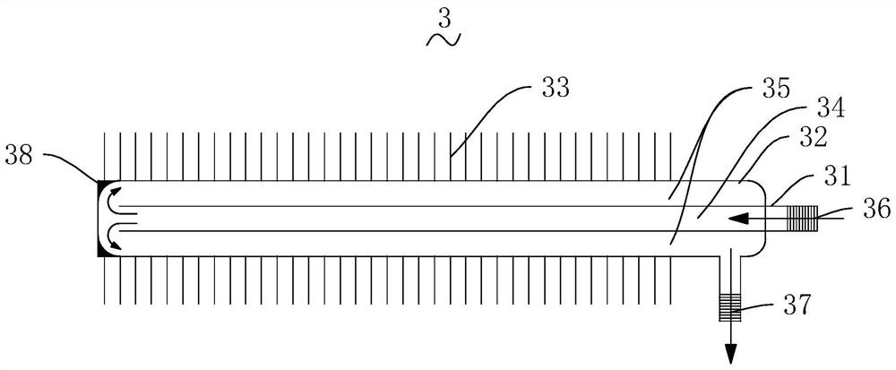
The invention discloses a tail gas purification system and method for recycling smoke waste heat. The system comprises a connecting water pipe, an inlet flue, a washing tower, a hot water storage tankand a hot water pump. A raw smoke heat taker is arranged in the inlet flue, a smoke inlet is formed in the tower wall of the washing tower, a smoke outlet is formed in the top of the washing tower, and a pipe grid layer, a washing and spraying layer, a desizing layer, a liquid receiving layer and a demisting heat taking layer are sequentially arranged in the position, between the smoke inlet andthe smoke outlet, of a tower body of the washing tower from bottom to top. The demisting heat taking layer, the pipe grid layer and the raw smoke heat taker are sequentially connected in series through water pipes. Smoke waste heat is recycled stage by stage through the raw smoke heat taker, the pipe grid layer and the demisting heat taking layer, and waste heat of low-grade industrial tail gas ina tail gas purification tower can be effectively reused.

Description

technical field [0001] This application relates to the field of new energy and energy saving, and specifically relates to a tail gas purification system and method for recovering waste heat from flue gas. Background technique [0002] The heat loss of the boiler is divided into the following five categories: flue gas loss, chemical incomplete combustion loss, mechanical incomplete combustion loss, heat dissipation loss, and ash physical heat loss. The heat that is taken away with the exhaust of the flue gas is called the heat loss of the flue gas. It is the largest item of boiler heat loss, about 4 to 8% of the total heat of combustion. The main factors affecting this loss are the flue gas volume and flue gas temperature. If the flue gas volume is large and the flue gas temperature is high, the flue gas The loss of heat taken away is also large. [0003] The main energy source in the production process of power stations and boilers is the heat energy released by fuel combu...

Claims


Application Information

Patent Timeline
IPC IPC(8): F23J15/00F28D21/00F28F1/00F23J15/06F23J15/04B01D53/78B01D53/26
CPCF23J15/006F28D21/001F28F1/00F23J15/06F23J15/04B01D53/78B01D53/265F28D2021/0024B01D2258/0283Y02E20/30
Inventor 程常杰李泽清张荣
Owner 杭州蕴泽环境科技有限公司
Learn More