
A lithium battery charging circuit and pcb board

A charging circuit and lithium battery technology, which is applied in battery circuit devices, circuit devices, battery overheating protection, etc., can solve problems such as easy tripping, failure to meet fast charging requirements, excessive transient current, etc., and achieve power-on tripping problems, avoiding battery overheating and burning, and improving service life

Active Publication Date: 2020-11-17
佛山市万发科技有限公司
View PDF7 Cites 0 Cited by
  • Summary
  • Abstract
  • Description
  • Claims
  • Application Information

AI Technical Summary

Problems solved by technology

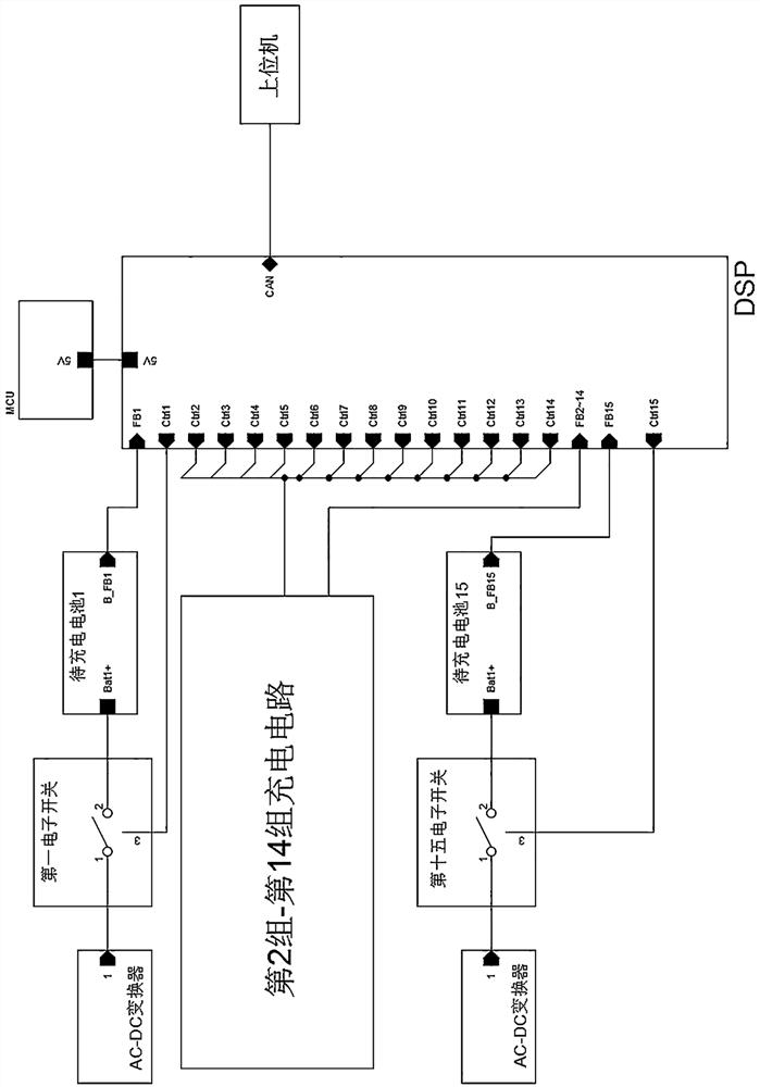
[0003] (1) A charging circuit structure capable of charging 15 lithium batteries at the same time, including 15 sets of charging circuits and processing devices, please refer to figure 1 , each group of charging circuits includes an AC-DC converter, an electronic switch and a battery to be charged, each group of charging circuits is electrically connected to the processing device, and the processing device controls the charging circuit to complete the charging task; because each group of charging circuits The charging tasks are all carried out independently. Assuming that the output of the AC-DC converter is 16.8V / 5A, the charging power of 15 sets of charging circuits at the same time is 16.8*5*15=1260W. When the power is turned on, the transient current is too large, which is easy Cause tripping, and will cause pollution to the grid, does not meet the green source requirements
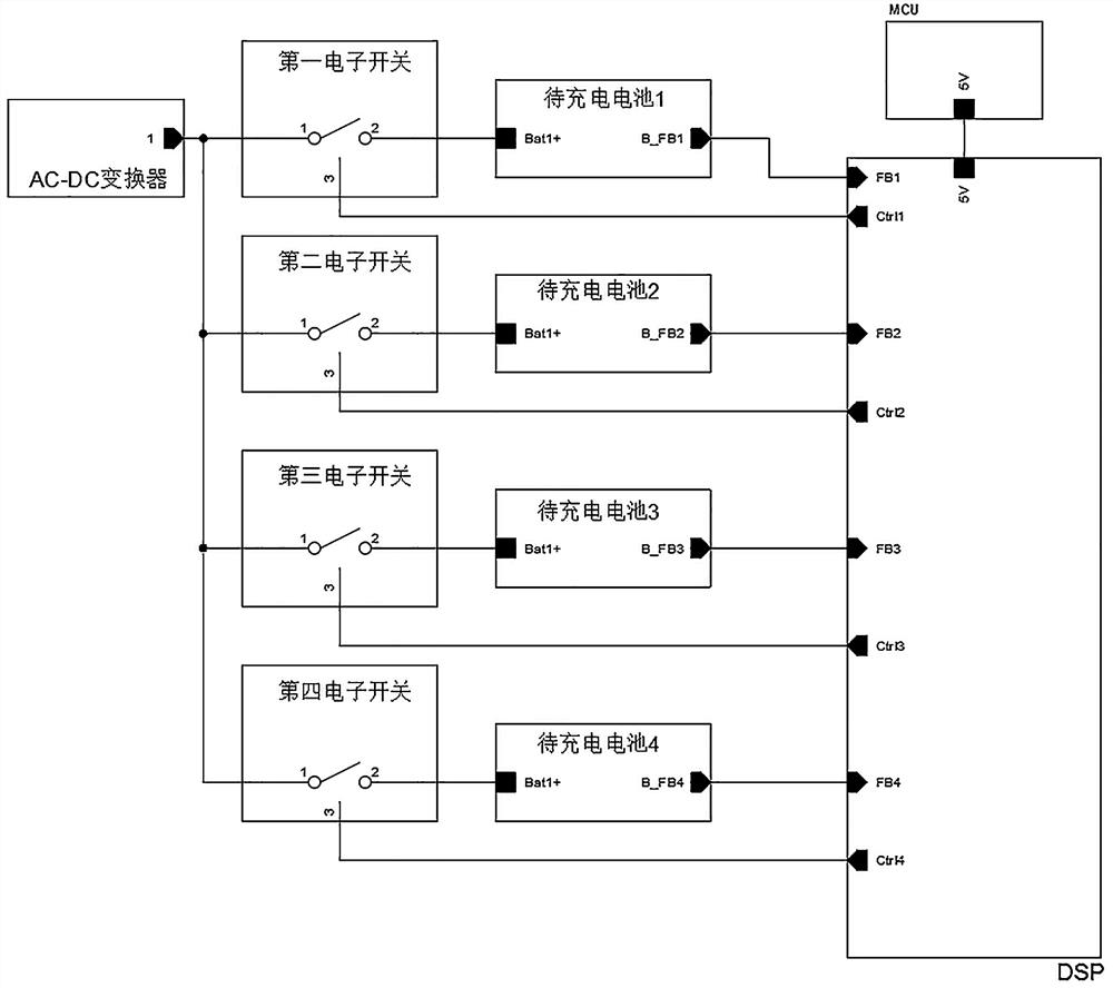
[0004] (2) A charging circuit structure for charging 4 lithium batteries, one charger charges the 4 batteries to be charged one by one, please refer to figure 2 , including 1 AC-DC converter, 4 electronic switches, 4 batteries to be charged and processing device; the AC-DC converter is respectively connected with 4 electronic switches, and the processing device is respectively connected with 4 electronic switches and 4 batteries to be charged are connected, and the processing device monitors the charging status of the 4 batteries to be charged and controls the on-off of the 4 electronic switches respectively; when the first battery to be charged is fully charged, the processing device controls the corresponding first electronic switch Disconnect and control the second electronic switch to close, and start charging the second battery to be charged. When the second battery to be charged is fully charged, the processing device controls the corresponding second electronic switch to be disconnected and controls the third battery to be charged. The electronic switch is closed, and so on, until the 4 batteries to be charged are all charged; since the batteries to be charged need to be charged one by one, the charging time is long, which cannot meet the fast charging requirements

Method used


Image

  • A lithium battery charging circuit and pcb board
  • A lithium battery charging circuit and pcb board
  • A lithium battery charging circuit and pcb board

Examples


Embodiment Construction

[0030] The present invention provides a lithium battery charging circuit and a PCB board. In order to make the purpose, technical solution and effect of the present invention more clear and definite, the present invention will be further described in detail below with reference to the accompanying drawings and examples.

[0031] In the description of the present invention, it should be understood that the terms "installation" and "connection" should be understood in a broad sense, and those of ordinary skill in the art can understand the specific meanings of the above terms in the present invention according to specific situations.

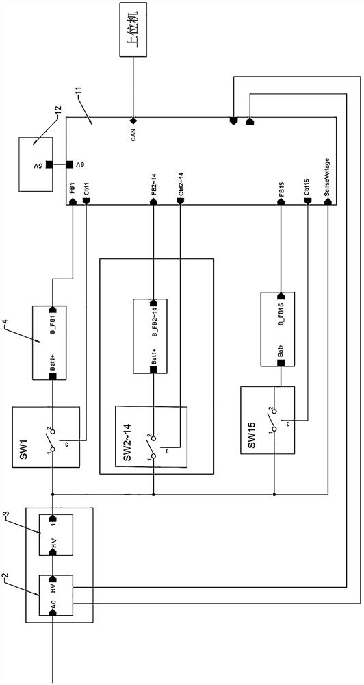
[0032] see Figure 3 to Figure 6 , the present invention provides a lithium battery charging circuit, including a power factor correction unit 2 for power factor adjustment, a DC-DC converter 3, an electronic switch, a battery pack to be charged 4 and a processing unit, the electronic switch The number is consistent with the number of battery pack...


PUM


Abstract

The invention discloses a lithium battery charging circuit and a PCB. The lithium battery charging circuit comprises a power factor correction unit used for power factor adjustment, a DC-DC converter,an electronic switch, a to-be-charged battery pack and a processing unit. The number of the electronic switches is consistent with that of to-be-charged battery packs, the electronic switches are inone-to-one correspondence with the to-be-charged battery packs, the power factor correction unit processes input voltage of an external high-power power supply and then outputs the input voltage to the DC-DC converter, and the power factor correction unit is electrically connected with the processing unit. The output end of the DC-DC converter is connected with a first port of the electronic switch and the processing unit, a second port of the electronic switch is connected with the input end of the corresponding to-be-charged battery pack, the output end of the to-be-charged battery pack is connected with the processing unit, and a third port of the electronic switch is connected with the processing unit. The lithium battery charging circuit provided by the invention can solve the problems of power-on tripping, interference of the charging process of the to-be-charged battery pack to a power grid and charging current equalization.

Description

technical field [0001] The invention relates to the technical field of battery charging management, in particular to a lithium battery charging circuit and a PCB board. Background technique [0002] The charging cabinet can charge multiple lithium batteries. The existing charging cabinet mainly uses the following two methods to complete the charging task: [0003] (1) A charging circuit structure capable of charging 15 lithium batteries at the same time, including 15 sets of charging circuits and processing devices, please refer to figure 1 , each group of charging circuits includes an AC-DC converter, an electronic switch and a battery to be charged, each group of charging circuits is electrically connected to the processing device, and the processing device controls the charging circuit to complete the charging task; because each group of charging circuits The charging tasks are all carried out independently. Assuming that the output of the AC-DC converter is 16.8V / 5A, th...

Claims


Application Information

Patent Timeline
Patent Type & Authority Patents(China)
IPC IPC(8): H02J7/00H02J7/02H02M1/14H02M1/42
CPCH02J7/0013H02J7/0029H02J7/02H02M1/14H02M1/4225H02J7/00304H02J7/00309H02J2207/20Y02B70/10
Inventor 洪育江
Owner 佛山市万发科技有限公司
Learn More