
T-girder flange slab tensioning joint under post-tensioned bonded prestressed ribbed slab and construction method

A technology of bonding prestressed and prestressed tendons, applied in the direction of floor slabs, joists, girders, etc., can solve the problems of reduced section bearing capacity, difficult construction, high slab surface, etc., to improve the mechanical characteristics and anti-negative bending of nodes Good moment effect and strong shock resistance

Inactive Publication Date: 2020-09-01
NANTONG SIJIAN CONSTR GRP
View PDF6 Cites 2 Cited by
  • Summary
  • Abstract
  • Description
  • Claims
  • Application Information

AI Technical Summary

Problems solved by technology

However, the joint joints (beam-column joints, beam-column joints, and column-column joints) have complex construction techniques and are difficult to construct, and become structural weak points that may be damaged. weak point
In particular, it is difficult to guarantee the construction quality of the core area of ​​such complex bonded prestressed beam-column joints
The beam-column core area of ​​such complex joints often has dense and intricately arranged steel bars, difficult to meet the anchorage length of the steel bars, difficult to control the welding quality with the rib plate, insufficient welding operation surface for the steel bars at the bottom of the beam, and difficult to control the opening ratio of the steel members. The superimposed arrangement of steel bars leads to construction problems such as super-high slabs

Method used


Image

  • T-girder flange slab tensioning joint under post-tensioned bonded prestressed ribbed slab and construction method

Examples


Embodiment 1

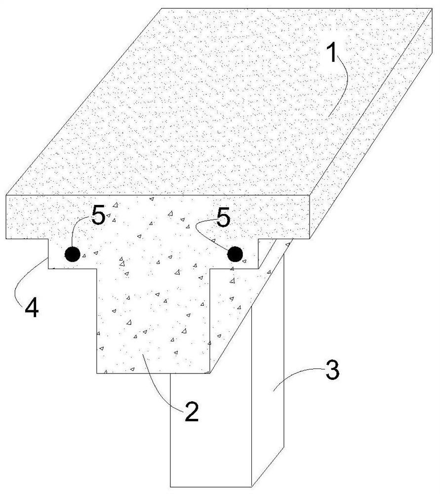
[0033] A post-tensioned T-beam flange tension node structure with bonded prestressed ribs, including a cast-in-place floor 1, a partial cast-in-place T-beam 2, a cast-in-place concrete column 3, and bonded prestressed steel bars 5; The cast-in-place T-beam 2 is arranged at the lower part of the cast-in-place floor 1; the partial cast-in-place T-beam 2 is connected with the cast-in-place concrete column 3; the two ends of the partial cast-in-place T-beam 2 are provided with prestressed tunnels and internal prestressed steel bars 5, The bonded prestressed tendons 5 constitute the tension end nodes of the cast-in-place T beam 2 prestressed tendons in later construction.

[0034] This embodiment effectively realizes the implementation of the new structure and new technology of the prestressed construction of the beam-column joints of the cast-in-place reinforced concrete structure.

[0035] In order to further explain this embodiment, it should be noted that the partial cast-in-pl...

Embodiment 2

[0038] A post-tensioning method has a bonded prestressed rib lower T-beam flange tension node and a construction method, and the specific steps are:

[0039] 1) Cast-in-place concrete column 3 reinforcement binding and formwork installation construction. In order to better complete the installation of the follow-up T-beam wing plate, the installation of the cast-in-place concrete column formwork must be completed first. When the cast-in-place concrete column is installed on site, the installation size of the T-beam wing plate under the follow-up plate must be considered at the top of the column. That is, the thickness of the T-beam wing plate is lowered at the joint of the column-beam joint to realize the effective docking of the installation of the local T-beam wing plate formwork protruding under the subsequent plate. The cast-in-place concrete column formwork adopts aluminum alloy formwork or wood formwork. After the cast-in-place concrete column formwork is installed, do ...


PUM


Abstract

The invention discloses a T-girder flange slab tensioning joint under a post-tensioned bonded prestressed ribbed slab and a construction method. The construction process flow comprises the following steps of 1) binding of cast-in-place concrete column steel bars and template mounting construction; 2) integral installation of a floor and a T-girder template bracket; 3) girder slab steel bar bindingand prestressed rib pipe insertion pavement; 4) pipe insertion treatment of T-girder flange slab end prestressed ribs under slabs; 5) overall casting and maintenance of slab column concrete; 6) tensioning and anchoring of prestressed ribs at the ends of T-girder flange slabs under the slabs; 7) passageway grouting and prestressed rib anchoring end anchor-sealing treatment; and 8) disassembly of the template bracket. According to the construction method, an under-slab T-girder flange slab end prestressed tensioning technology is adopted at a cast-in-place concrete beam-column joint, so that the beam-column joint stress characteristic is improved effectively; the joint is high in hogging moment resistance; and the prestressed beam-column reinforced joint is high in shock resistance.

Description

technical field [0001] The invention relates to a connection node structure and a construction method of a prestressed structure, in particular to a tension node of a T-beam wing plate under a bonded prestressed rib plate by a post-tensioning method and a construction method. Background technique [0002] With the continuous development of my country's construction industry, the expectations of the latter for large-scale commercial complex projects are also increasing. "Normal service limit state" has a deeper understanding and requirements. However, the joint joints (beam-column joints, beam-column joints, and column-column joints) have complex construction techniques and high construction difficulties, and become structural weak points that may be damaged, and the joint joint surface becomes the place where the bearing capacity of the section decreases. weak side. In particular, it is difficult to guarantee the construction quality of the core area of ​​such complex bonde...

Claims


Application Information

Patent Timeline
Patent Type & Authority Applications(China)
IPC IPC(8): E04B5/32E04C3/26E04C3/34E04C5/08E04G21/00E04G21/12
CPCE04B5/32E04C3/26E04C3/34E04C5/08E04G21/00E04G21/12
Inventor 张卫国徐卓陈学军丁伟王斯海
Owner NANTONG SIJIAN CONSTR GRP
Learn More